EasyManuals Logo

CHK Power Quality MIRO PQ25 User Manual

CHK Power Quality MIRO PQ25
222 pages
To Previous Page IconTo Previous Page
Page #222 background imageLoading...
Page #222 background image
CHK Power Quality Pty Ltd, User Manual Miro Power Quality Logger and Analyser, 15 August 2016
Website: www.chkpowerquality.com.au; Enquiries: sales@chkpowerquality.com.au; Page 222
Address: Unit 1, 3 Tollis Place, Seven Hills, NSW 2147, Sydney, Australia; ABN: 53 169 840 831; Telephone: +61 2 8283 6945;
Fax: +61 2 8212 8105; Website: www.chkpowerquality.com.au
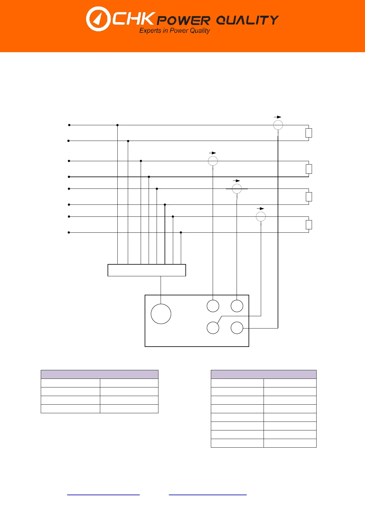
11.5.2 4 independent circuits (VL8 cable)
a. Connection diagram using 8-Wire Voltage Cable (VL8).
b. NC (not connected).
Circuit summary table
Voltage lead connection
Source
Generic
Phase A
Phase A
Load
4 Single phases
Neutral A
Neutral A
Connection type
Star/Wye
Phase B
Phase B
Nominal RMS
Phase-Neutral
Neutral B
Neutral B
Phase C
Phase C
Neutral C
Neutral C
Gnd
Gnd
Neutral
Neutral
Voltage
Current
A
B
C
N
A Line
VL8
B Line
C Line
A
Neutral A
B
C
Neutral C
Neutral B
Load
Source
GND Line
Neutral
Gnd

Table of Contents

Questions and Answers:

Question and Answer IconNeed help?

Do you have a question about the CHK Power Quality MIRO PQ25 and is the answer not in the manual?

CHK Power Quality MIRO PQ25 Specifications

General IconGeneral
BrandCHK Power Quality
ModelMIRO PQ25
CategoryMeasuring Instruments
LanguageEnglish