CHK Power Quality Pty Ltd, User Manual – Miro Power Quality Logger and Analyser, 15 August 2016
Website: www.chkpowerquality.com.au; Enquiries: sales@chkpowerquality.com.au; Page 9
Address: Unit 1, 3 Tollis Place, Seven Hills, NSW 2147, Sydney, Australia; ABN: 53 169 840 831; Telephone: +61 2 8283 6945;
Fax: +61 2 8212 8105; Website: www.chkpowerquality.com.au
1.1.1.8 Transformer monitoring
The incorporation of two temperature channels ideally lends the instrument to transformer
monitoring applications. Additional measurements specific to transformer monitoring are
available upon request.
1.1.1.9 DC system monitoring
Each current and voltage channel (using the appropriate current probe) can also measure
DC components and hence extends the instrument applications to photovoltaic and railway
systems.
1.1.1.10 Model category
Two model categories: Single phase and three phase versions.
Single phase:
o PQ25 (2 voltage and 2 current channels).
3 phase:
o PQ35 (3 voltage and 4 current channels).
o PQ45 (4 voltage and 4 current channels).
1.1.1.11 Expansion port
This port allows for system expansion to include additional sensors, input/output controls
and custom interfaces.
1.1.1.12 Accessories
ALL Powermonic PM35 and PM45 accessories can be used with the PQ35 and PQ45
models respectively.
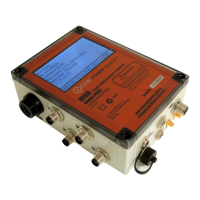
1.1.2 Connections and interfaces
Photos in figures 1.1.2.1, 1.1.2.2, 1.1.2.3 and 1.1.2.4 show ports and hardware interfaces.
A: Voltage lead connector. It can accommodate up to four (4) voltages.
B: Current probe connectors. The channels are designated as A, B, C, and N to
accommodate three phase systems. The current channels can accept Rogowski coils,
clamp-on CTs and DC probes.
C: Graphical liquid crystal display (LCD). The LCD can be configured to display pages with
each page displayed for approximately three seconds. The pages commence to display
upon the application of power. Each page includes
D: Data (USB) connector (top); External DC power (bottom).
E: Temperature connectors. Two external temperatures are available for correlating PQ data
and temperature measurements.
F: Expansion port. Used for USB communications and for an external power adaptor.
G: GPS antenna (left); Cellular antenna (right).
 Loading...