9-7
Cisco SCE8000 GBE Installation and Configuration Guide
OL-19897-02
Chapter 9 Removal and Replacement Procedures
Removing and Replacing the Power Supply
Removing a DC-Input Power Supply
Warning
Before performing any of the following procedures, ensure that power is removed from the DC circuit.
Warning
Voltage is present on the backplane when the system is operating. To reduce risk of an electric shock,
keep hands and fingers out of the power supply bays and backplane areas.
Step 1 Verify that power is off to the DC circuit connected to the DC-input power supply you are removing.
Step 2
Remove the four screws securing the terminal block cover, and slide the cover off the terminal block
(Figure 9-3).
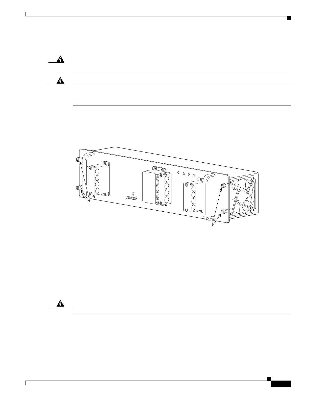
Figure 9-3 DC-Input Front Panel for 2700-W DC-Input Power Supply
Step 3
Remove the two screws securing each of the cable holder covers, and remove the cable holder covers off
the cable holders.
Step 4 Disconnect the DC-input wires from the terminal block.
Always disconnect the DC-input wires in this order:
• Positive (+)
• Negative (-)
• Ground
Warning
When installing the unit, the ground connection must always be made first and disconnected last.
Step 5 Remove the two tie-wraps from the ground cable. If there is a long cable tie securing the cable holders,
remove that as well.
Step 6 Loosen the captive installation screws on the power supply.
132218
Captive installation
screws
Captive installation
screws
PWR-2700-DC/4
-VE-1
-VE-1
-VE-2
-VE-2
IN
PU
T1
O
K
48V-60V
=40A
IN
PU
T2
O
K
48V
-60V
=40A
FA
N
O
K
O
U
TP
U
T
FA
IL
ALL FASTENERS MUST BE FULLY ENGAGED
PRIOR TO OPERATING THE PO
W
ER SUPPLY