6-6
Cisco SCE8000 GBE Installation and Configuration Guide
OL-19897-02
Chapter 6 Cabling the GBE Line Ports and Completing the Installation
Cabling the GBE Line Interface Ports
Cabling the GBE Line Interface Ports
Note When installing an External Optical Bypass module, the Cisco SCE8000 GBE line ports are connected
to the module. See Cabling the Line Interface Ports: Using the External Optical Bypass Module,
page 6-9 for complete instructions.
Warning
Class 1 laser. Avoid exposure to radiation and do not stare into open aperture.
• SFP Module Cabling and Connection Equipment, page 6-7
• How to Cable the GBE Line Interface Ports, page 6-9
• Cabling the Line Interface Ports: Using the External Optical Bypass Module, page 6-9
C2 SPA port 3/1/2 5
D2 SPA port 3/1/3 5
CTRL (use the short leg of the ‘Y’
control cable labeled OPB CTRL1)
right-hand 'Optical Bypass' port on Cisco
SCE8000-SCM-E module (use the long leg of
the ‘Y’ control cable; it is labeled SCE8000
GBE -2L BYPASS)
5
External bypass module #4
A1 Subscriber side network element 6 6
B1 Network side network element 6 6
C1 SPA port 3/1/4 6
D1 SPA port 3/1/5 6
A2 Subscriber side network element 7 7
B2 Network side network element 7 7
C2 SPA port 3/1/6 7
D2 SPA port 3/1/7 7
CTRL (use the short leg of the ‘Y’
control cable labeled OPB CTRL2)
right-hand 'Optical Bypass' port on Cisco
SCE8000-SCM-E module (use the long leg of
the ‘Y’ control cable; it is labeled SCE8000
GBE -2L BYPASS)
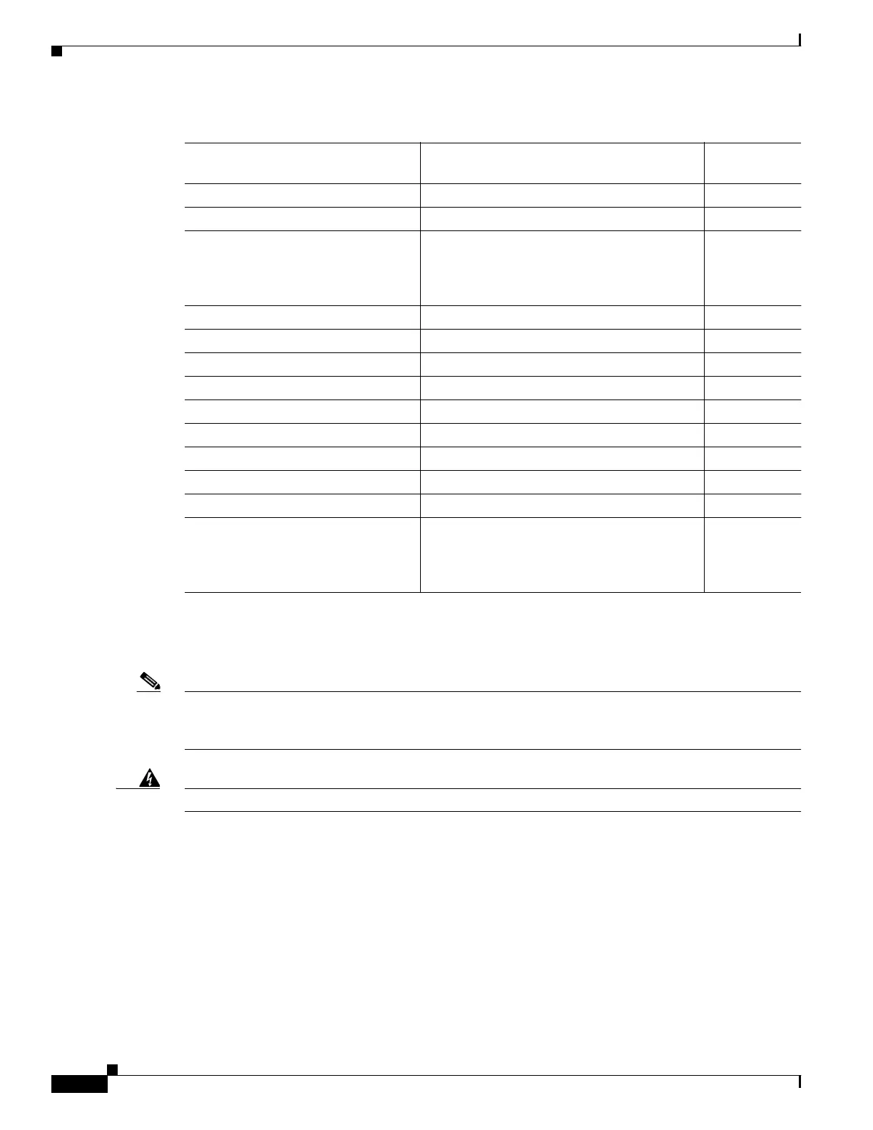
Table 6-2 Optical Bypass Module Connectivity (continued)
Connect this port on the external
bypass module. To this component Link number