2-11
Cisco SCE8000 GBE Installation and Configuration Guide
OL-19897-02
Chapter 2 Introduction to the Cisco SCE8000 GBE Platform
The Cisco SCE8000 GBE Optical Bypass
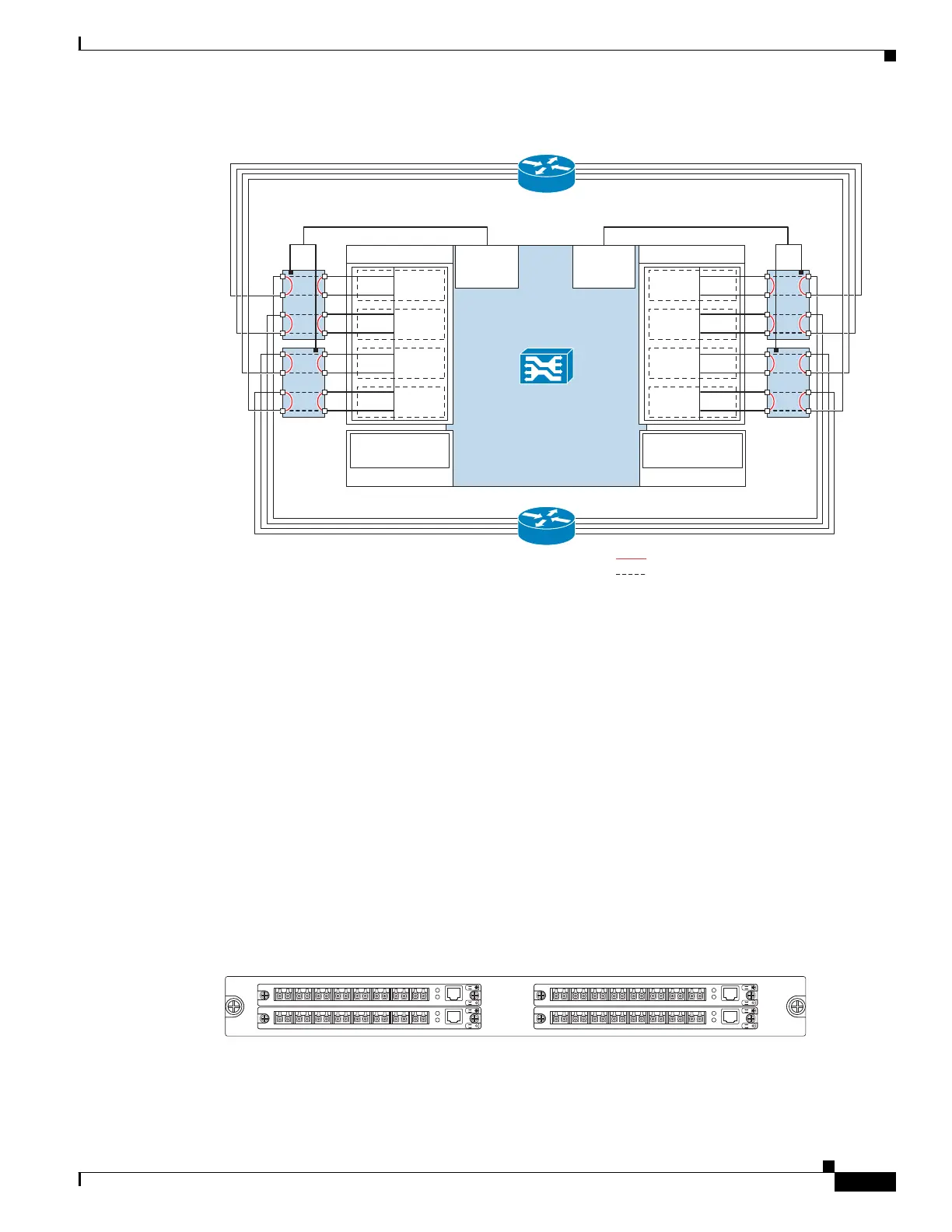
Figure 2-6 Optical Bypass Module Connectivity: SCE8000 GBE
Optical Bypass Module (OPB-SCE8K-2L)
There are two types of optical bypass modules to support different optic types:
• OPB-SCE8K-2L-SM supports Single-Mode optics and should be used with SCE8000 GBE
equipped with Single-Mode optics.
• OPB-SCE8K-2L-MM supports Multi-Mode optics and should be used with SCE8000 GBE
equipped with Multi-Mode optics.
The optical bypass module is installed either internally, in slot #4 of the Cisco SCE8000 GBE chassis
or in an external mounting panel in the rack.
Up to four optical bypass modules can be mounted internally, supporting inline insertion into all eight
links.
Figure 2-7 displays the Optocal Bypass Module. Table 2-9 lists the Optical Bypass Module ports and
Table 2-10 describes the Optical Bypass Module LEDs.
Figure 2-7 Optical Bypass Module
274443
SCE8000 GBE
Traffic GBE SPA 1
1/0–S
1/1–N
L4
1/2–S
1/3–N
L5
1/4–S
1/5–N
L6
1/6–S
1/7–N
L7
0/0–S
0/1–N
L0
0/2–S
0/3–N
L1
0/4–S
0/5–N
L2
0/6–S
0/7–N
L3
Cascade 10GBE
SPA 3
3/0-cascade
Traffic GBE SPA 0
Cascade 10GBE
SPA 2
2/0-cascade
OPB
OPB
OPB
OPB
External
bypass
connector
External
bypass
connector
Dual OPB control cable Dual OPB control cable
Network side
(upstream)
Subscriber side
(downstream)
Default bypass state (power off)
Non default bypass state (power on)
274950
CTRL
A1
Rx Tx
B1 C1 D1 A2 B2 C2 D2
L2
L1
A
B
C
D
A
C
B
D
OPB-SCE8K-2L-MM
CTRL
A1
Rx Tx
B1 C1 D1 A2 B2 C2 D2
L2
L1
A
B
C
D
A
C
B
D
OPB-SCE8K-2L-MM
CTRL
A1
Rx Tx
B1 C1 D1 A2 B2 C2 D2
L2
L1
A
B
C
D
A
C
B
D
OPB-SCE8K-2L-MM
CTRL
A1
Rx Tx
B1 C1 D1 A2 B2 C2 D2
L2
L1
A
B
C
D
A
C
B
D
OPB-SCE8K-2L-MM
0
2
1
3
OP88K-HD-EXT-PNL