3-5
Cisco SCE8000 GBE Installation and Configuration Guide
OL-19897-02
Chapter 3 Cisco SCE8000 GBE Topology and Topology-Related Parameters
Physical Topologies
Receive-only Topology
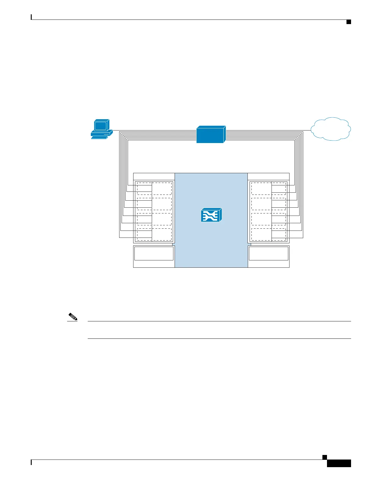
In this topology, an optical splitter resides physically on the link between the subscribers and the
network. The traffic passes through the optical splitter, which splits traffic to the Cisco SCE8000 GBE
GBE. The Cisco SCE8000 GBE , therefore, only receives traffic and does not transmit. Figure 3-3
displays the receive-only topology.
Figure 3-3 Receive-only Topology
When configuring the Cisco SCE8000 GBE GBE, an optical splitter topology is referred to as
“receive-only” connection mode.
Note that in an optical splitter topology, the Cisco SCE8000 GBE only enables traffic monitoring
functionality.
Note When implementing receive-only topologies with a switch, the switch must support SPAN functionality
that includes separation between ingress and egress traffic and multiple SPAN-ports destinations.
Dual Cisco SCE8000 GBE Topology (Cascade)
In this topology, two cascaded Cisco SCE8000 GBE s are used. This allows a fail-over solution, where
in case of a failure of one Cisco SCE8000 GBE the functionality that the Cisco SCE8000 GBE provides
is preserved by the redundant platform.
Subscriber
275784
Network
SCE8000 GBE
Traffic GBE SPA 1
1/0–S
1/1–N
L4
1/2–S
1/3–N
L5
1/4–S
1/5–N
L6
1/6–S
1/7–N
L7
0/0–S
0/1–N
L0
0/2–S
0/3–N
L1
0/4–S
0/5–N
L2
0/6–S
0/7–N
L3
Cascade 10GBE
SPA 3
3/0-cascade
Traffic GBE SPA 0
Cascade 10GBE
SPA 2
2/0-cascade
Splitter