3-6
Cisco SCE8000 GBE Installation and Configuration Guide
OL-19897-02
Chapter 3 Cisco SCE8000 GBE Topology and Topology-Related Parameters
Physical Topologies
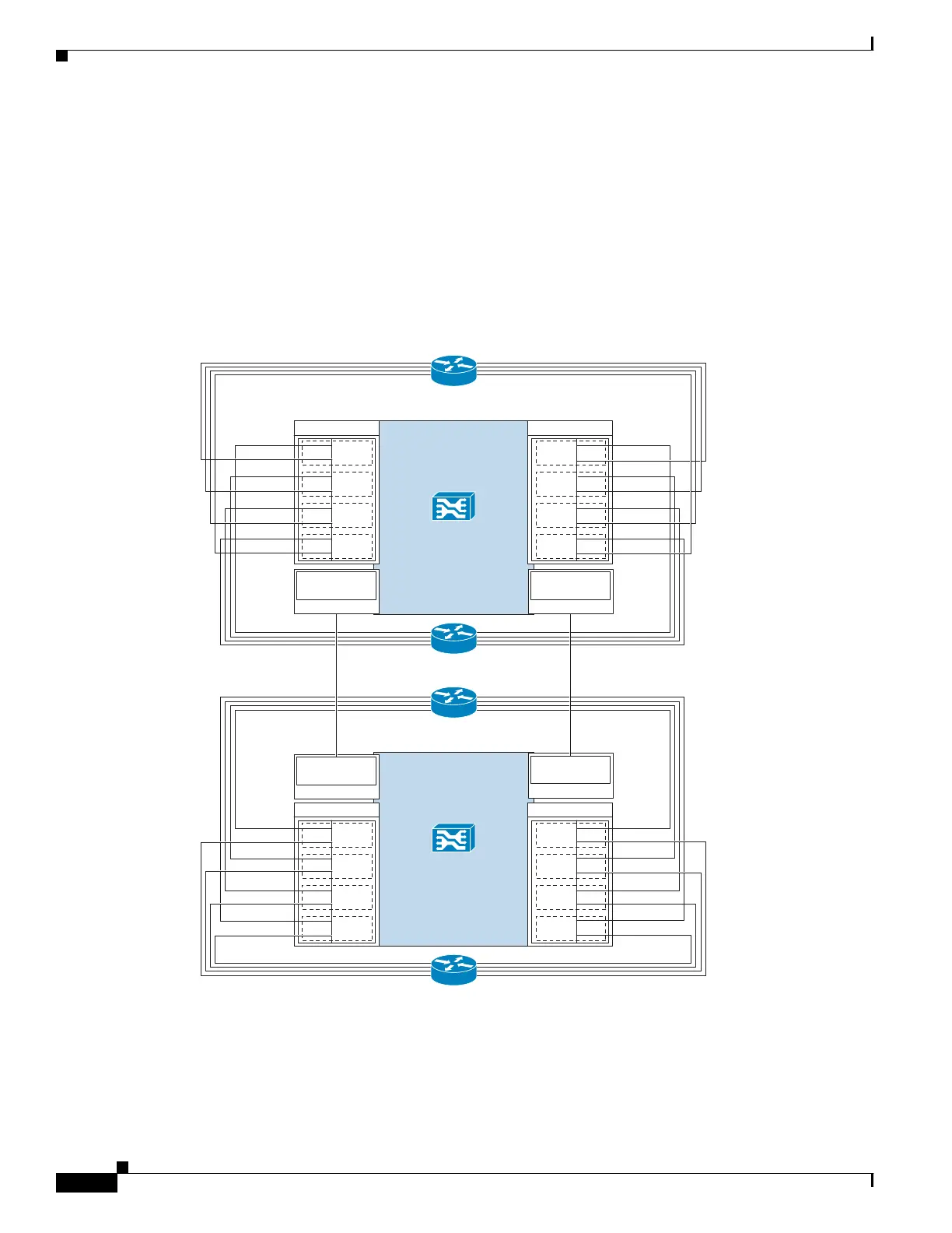
This topology allows both control and monitoring functionality where redundancy is required and
“inline” connection is used. The two Cisco SCE8000 GBE s are cascaded, so the active Cisco SCE8000
GBE processes the traffic of the two links, while the standby Cisco SCE8000 GBE only bypasses the
traffic of its links to the active Cisco SCE8000 GBE for processing, and then bypasses the processed
traffic back to the link. The two Cisco SCE8000 GBE s also exchange keep-alive messages and
subscriber state information.
In case the active Cisco SCE8000 GBE fails, the two Cisco SCE8000 GBE s switch their roles, and this
way fail-over is provided. Figure 3-4 displays the two cascaded Cisco SCE8000 GBE platforms
topology.
Figure 3-4 Two Cascaded Cisco SCE8000 GBE Platforms
274441
SCE8000 GBE
Traffic GBE SPA 1
1/0–S
1/1–N
L4
1/2–S
1/3–N
L5
1/4–S
1/5–N
L6
1/6–S
1/7–N
L7
0/0–S
0/1–N
L0
0/2–S
0/3–N
L1
0/4–S
0/5–N
L2
0/6–S
0/7–N
L3
Traffic GBE SPA 0
Network side
(upstream)
Subscriber side
(downstream)
SCE8000 GBE
Traffic GBE SPA 1
1/0–S
1/1–N
L4
1/2–S
1/3–N
L5
1/4–S
1/5–N
L6
1/6–S
1/7–N
L7
0/0–S
0/1–N
L0
0/2–S
0/3–N
L1
0/4–S
0/5–N
L2
0/6–S
0/7–N
L3
3/0-cascade
Traffic GBE SPA 0
2/0-cascade
Subscriber side
(downstream)
Network side
(upstream)
Cascade 10GBE
SPA 2
2/0-cascade
Cascade 10GBE
SPA 2
Cascade 10GBE
SPA 3
3/0-cascade
Cascade 10GBE
SPA 3