5-2
Cisco SCE8000 GBE Installation and Configuration Guide
OL-19897-02
Chapter 5 Connecting the Management Interfaces
Initial Setup Parameters
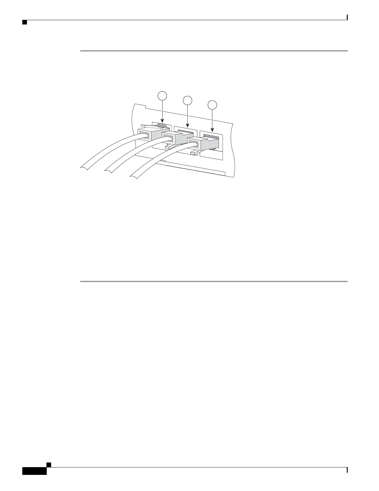
Step 1 Plug the RS-232 serial cable provided with the Cisco SCE8000 GBE into the CON port on the front
panel of the SCE8000-SCM-E. (See item #2 in Figure 5-1 below.)
Figure 5-1 Connecting the Local Console to the SCE8000-SCM-E CON Port
Make sure that you push on the RJ-45 connector (attached to the RS-232 serial cable) until you hear a
“click”, which indicates that the connector is fully inserted and secured in the receptacle. Gently pull on
the plug to confirm whether the plug is locked into the socket.
Step 2 Connect the other end of the serial cable (with an attached DB-9 or DB-25 connector) to the VT100
compatible local (serial) terminal.
Step 3 Make sure the local terminal is configured as a VT-100 terminal, according to the fixed Cisco SCE8000
GBE CON port parameters.
Step 4 Make sure that the Cisco SCE8000 GBE is powered-on, and has been allowed to complete booting (this
process may take several minutes).
Step 5 Press Enter several times until the Cisco logo appears on the local terminal.
Initial Setup Parameters
At this point there are several basic global parameters that must be correctly configured in order for the
SCE platform to communicate properly with the outside world. The following is a very brief summary
of the initial setup parameters and commands. For more information, refer to the Cisco SCE8000 GBE
Software Configuration Guide.
• IP address and subnet mask of the Cisco SCE8000 GBE platform itself. This is the IP address used
by the GBE management interface.
• IP address of the default gateway.
• Hostname—The hostname is used to identify the SCE platform. It appears as part of the CLI prompt
and is also returned as the value of the MIB-II object sysName.
–
The maximum length is 20 characters.
–
The default hostname is SCE8000 GBE.
270976
S
CE
8000-SC
M-
E
10
/100
/
10
00
LIN
K
/
ACTI
V
E
OPTICAL
BYPA
SS1
CO
NS
O
LE
PO
R
T1
1
2
3