3-8
Cisco SCE8000 GBE Installation and Configuration Guide
OL-19897-02
Chapter 3 Cisco SCE8000 GBE Topology and Topology-Related Parameters
Link Continuity
• Under certain types of failure within the SIP module, the SPA cards, or the XFP optic modules.
External Optical Bypass
When a separate bypass mechanism is required, an external optical bypass device can be used to provide
dependable link continuity. The external optical bypass device can be installed either inside the Cisco
SCE8000 GBE chassis or be rack-mounted externally. The external optical bypass device can also be
controlled manually by specific CLI commands.
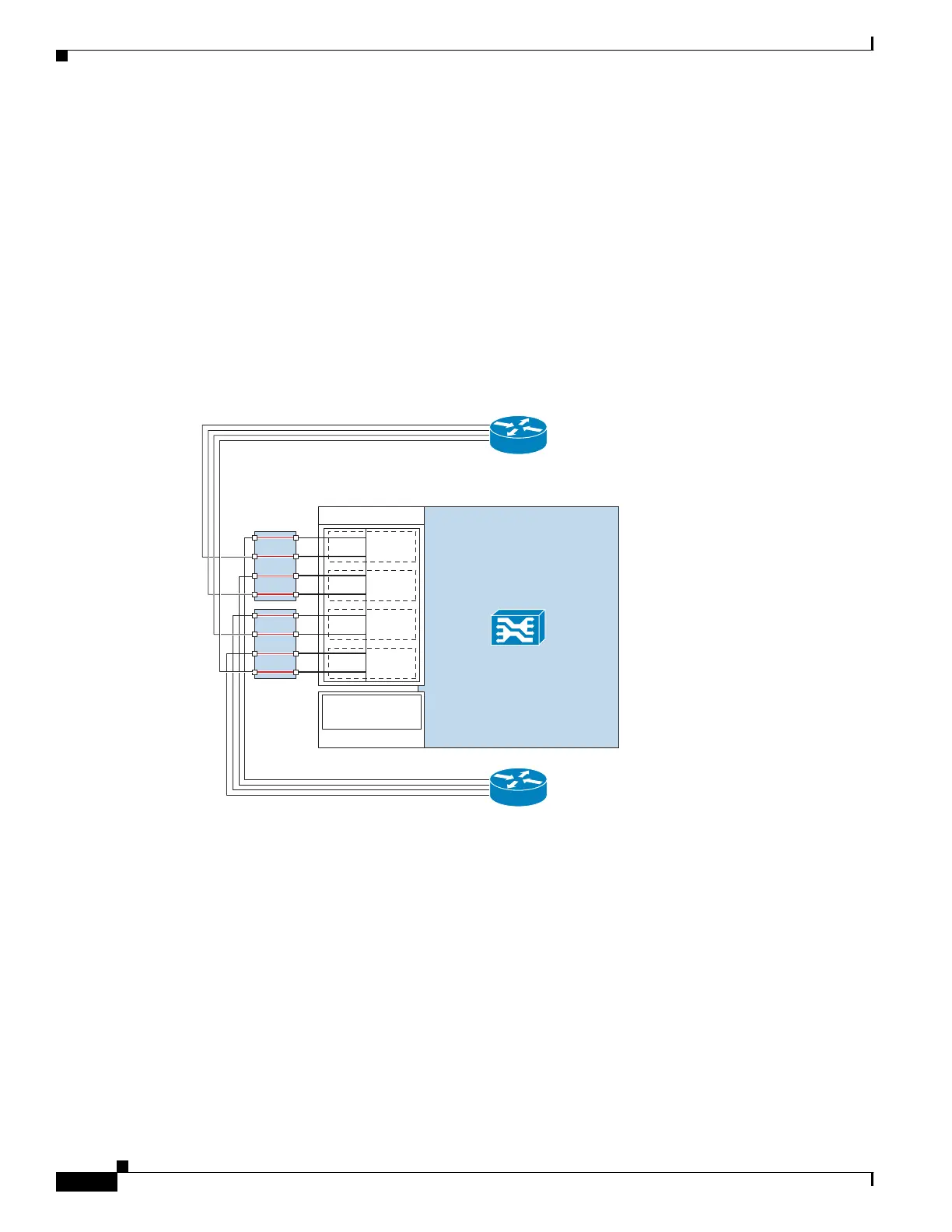
Under normal operating conditions, traffic flows through the link as usual, with the exception that the
optical bypass module sits on the link. Figure 3-5 displays the optical bypass under the normal operating
condition.
Figure 3-5 Optical Bypass Under Normal Operating Condition
275786
SCE8000 GBE
0/0–S
0/1–N
L0
0/2–S
0/3–N
L1
0/4–S
0/5–N
L2
0/6–S
0/7–N
L3
Traffic GBE SPA 0
Cascade 10GBE
SPA 2
2/0-cascade
OPB
OPB
Network side
(upstream)
Subscriber side
(downstream)