3-9
Cisco SCE8000 GBE Installation and Configuration Guide
OL-19897-02
Chapter 3 Cisco SCE8000 GBE Topology and Topology-Related Parameters
Link Continuity
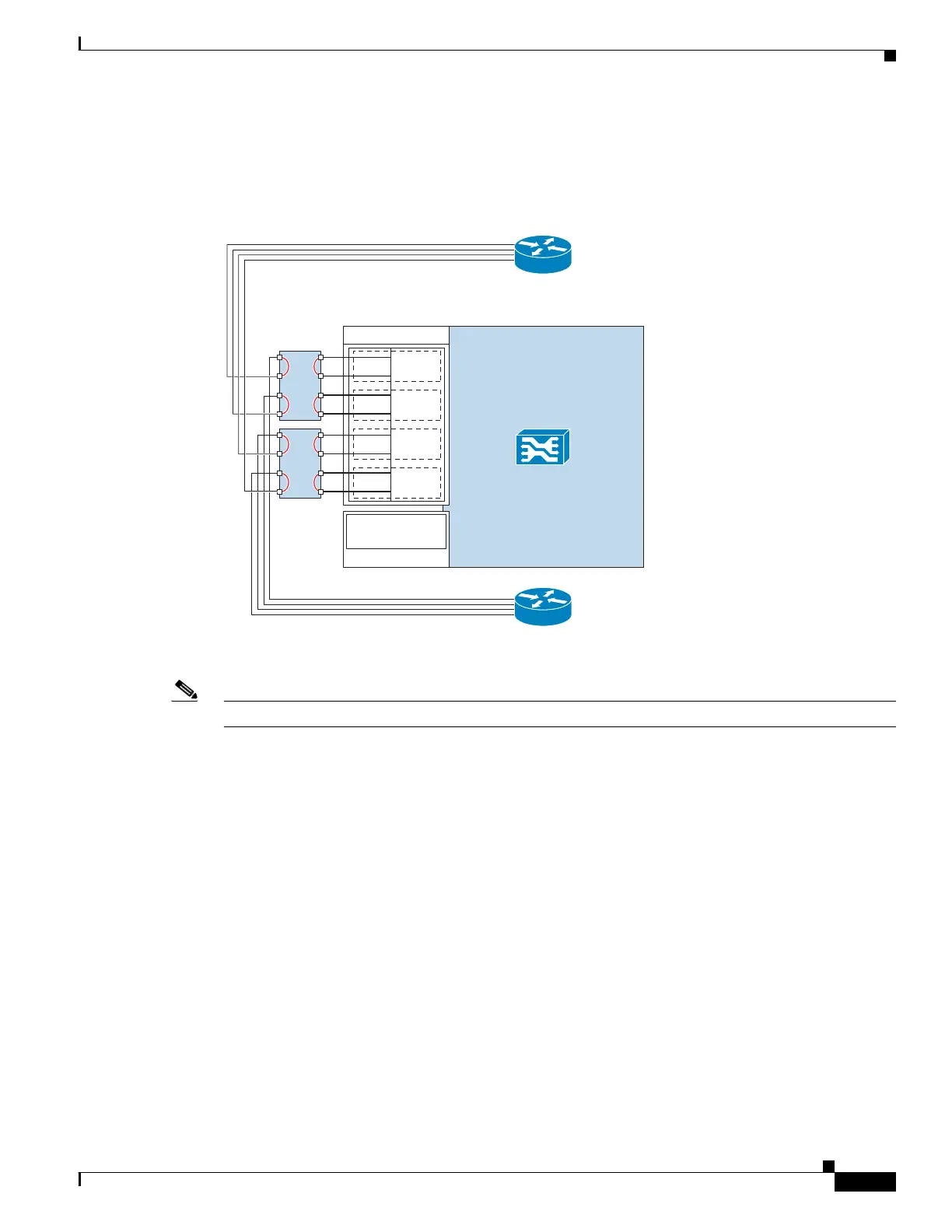
If the SCE8000 GBE platform fails, traffic flows through the optical bypass module, bypassing the
SCE8000 GBE , so that traffic on the link is maintained. Figure 3-6 displays the optical bypass under
failure conditions.
Figure 3-6 Optical Bypass Under Failure Conditions
Note In cascade configuration, installation of the optical bypass module is highly recommended.
This optical bypass module can be added to link without altering the basic characteristics of the topology.
(The installation procedure and the actual connections are somewhat different when the optical bypass
module is used, see Optical Bypass Module Connectivity, page 6-5.)
For more information regarding the external bypass module, refer to The Cisco SCE8000 GBE Optical
Bypass, page 2-10.
275785
SCE8000 GBE
0/0–S
0/1–N
L0
0/2–S
0/3–N
L1
0/4–S
0/5–N
L2
0/6–S
0/7–N
L3
Traffic GBE SPA 0
Cascade 10GBE
SPA 2
2/0-cascade
OPB
OPB
Network side
(upstream)
Subscriber side
(downstream)