6-2
Cisco SCE8000 GBE Installation and Configuration Guide
OL-19897-02
Chapter 6 Cabling the GBE Line Ports and Completing the Installation
Connecting the GBE Line Ports to the Network
Connecting the GBE Line Ports to the Network
Single Cisco SCE8000 GBE Topologies
In this topology, one or two 8-port GBE SPAs are installed in the Cisco SCE8000 GBE to support a
maximum of eight full duplex GBE links. The Cisco SCE8000 GBE may be either inline, to support
both monitoring and traffic control functionality, or receive-only for traffic monitoring functionality
only.
Guidelines for single SCE8000 GBE topologies:
• If only one SPA module (four links) is installed, it must be installed in bay 0 of the SPA jacket card.
• If two SPA modules (eight links) are installed, they must be installed in bays 0 and 1 of the SPA
jacket card.
A maximum of two SPAs is supported.
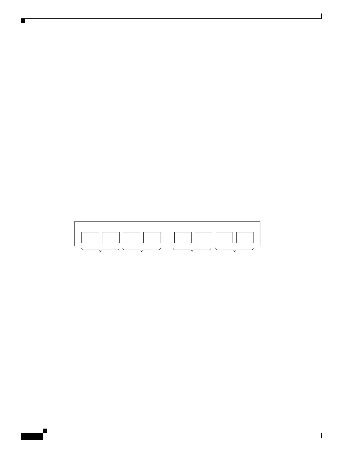
• The GBE SPA ports are connected in adjacent pairs.
Even ports (0,2,4,6) are the subscriber ports and the neighboring odd ports (1,3,5,7) are the network
ports.
Figure 6-1 displays the Cisco SCE8000 GBE port numbering.
Figure 6-1 Cisco SCE8000 GBE Port Numbering
•
Inline topologies require both Receive and Transmit fibers.
• Receive-only topologies use only Receive fibers.
• If link continuity needs to be maintained at all times when using the inline topology, optical bypass
modules should be installed, as follows:
–
8-port GBE SPA in subslot 0 only: two external bypass modules installed in the left side of slot
#4 of the SCE8000 GBE GBE
–
8-port GBE SPA in subslots 0 and1: four external bypass modules installed in slot #4 of the
SCE8000 GBE (slot #4 is fully populated)
274442
Sub Net Sub Net Sub Net Sub Net
GBE
Link 1
GBE
Link 2
GBE
Link 3
GBE
Link 4