9-15
Cisco SCE8000 GBE Installation and Configuration Guide
OL-19897-02
Chapter 9 Removal and Replacement Procedures
Removing and Replacing Modules
Installing a Module
Step 1 Choose a slot for the module.
Modules must be installed in the proper slots, as follows:
• A single SCE8000-SCM-E module must be installed in slot #1.
• If a second SCE8000-SCM-E module is used, it must be installed in slot #2.
• The SCE8000-SIP module must be installed in slot #3.
Step 2 At the SCE# prompt, type reload shutdown and press Enter to power down the Cisco SCE8000 GBE
platform before installing or removing any module.
Step 3 Make sure that there is enough clearance to accommodate any interface equipment that you will connect
directly to the module ports.
Step 4 Verify that the captive installation screws are tightened on all modules already installed in the chassis to
ensure that the EMI gaskets on all modules are fully compressed in order to maximize the opening space
for the new or replacement module.
Note If the captive installation screws are loose, the EMI gaskets on the installed modules will push adjacent
modules toward the open slot, reducing the opening size and making it difficult to install the replacement
module.
Step 5 Remove the module filler plate by removing the two Phillips pan-head screws from the filler plate. To
remove a module, follow the procedure in Removing a Module, page 9-18
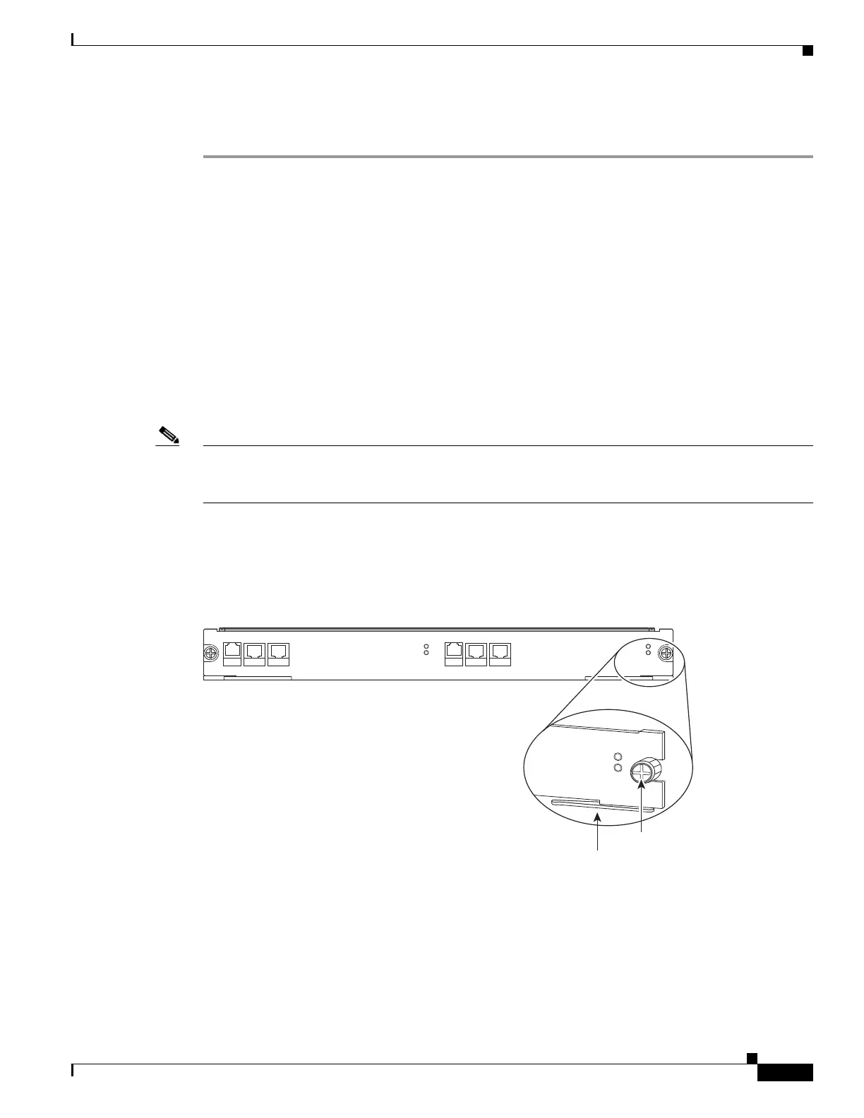
Step 6 Fully open both ejector levers on the new module. (See Figure 9-10.)
Figure 9-10 Ejector Levers and Captive Installation Screws
SCE8000 EXTENDED SERVICE CONTROL MODULE
SCE8000-SCM-E
STATUS
OPTICAL BYPASS
MASTER
SYSTEM POWER
10/100/
1000
LINK/
ACTIVE
OPTICAL
BYPASS1
CONSOLE PORT1
10/100/
1000
LINK/
ACTIVE
OPTICAL
BYPASS2
AUX PORT2
270901
Ejector lever
SCE8000 EXTE
N
DE
D SE
RVICE CONTRO
L MODULE
M
AS
TER
S
YSTEM PO
W
E
R
Captive
installation
screws