6-9
Cisco SCE8000 GBE Installation and Configuration Guide
OL-19897-02
Chapter 6 Cabling the GBE Line Ports and Completing the Installation
Cabling the GBE Line Interface Ports
How to Cable the GBE Line Interface Ports
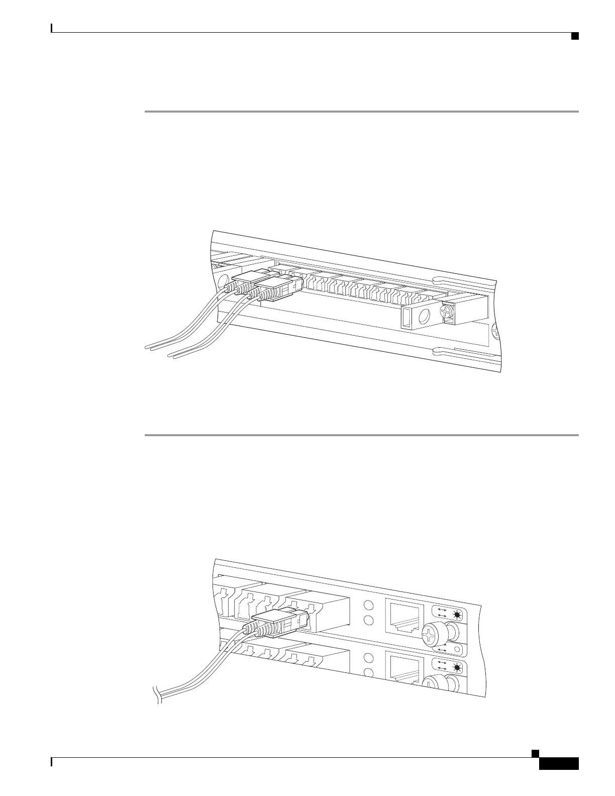
Step 1 Take the appropriate fiber optic cable (see SFP Module Cabling and Connection Equipment, page 6-7)
and plug it into the appropriate port on the SPA module in slot #3 of the Cisco SCE8000 GBE. (See
Figure 6-2 below.)
Make sure to push on the connector until you hear a click, which indicates that the connector is fully
inserted and secured in the receptacle. Always make sure that you insert the connector completely into
the socket.
Figure 6-2 Cabling the GBE Line Interface
Step 2
Verify that the link LED is green.
If the link LED does not light, try removing the network cable plug and reinserting it firmly into the
module socket.
Cabling the Line Interface Ports: Using the External Optical Bypass Module
Refer to Optical Bypass Module Connectivity, page 6-5 for specific connectivity. Figure 6-3 displays the
External Optical Bypass Module line interfaces.
Figure 6-3 External Optical Bypass Module Line Interfaces: SCE8000 GBE
275806
S
T
ATU S
SPA
-1
X1
0GE-L-V2
1
3
S
T
ATU
S
7
A
/L
STATU
S
SP
A
-
1
X1
0GE-L-V2
SPA-8X1GE-V2
3
4
STATU
S
2
1
0
A/L
5
6
7
A
/
L
A/L
A
/
L
A/L
A
/
L
A
/
L
A
/L
CTRL
B2 C2 D2
L2
L1
A
B
C
D
A
C
B
D
CTRL
B2 C2 D2
L2
L1
A
B
C
D
A
B