9-12
Cisco SCE8000 GBE Installation and Configuration Guide
OL-19897-02
Chapter 9 Removal and Replacement Procedures
Removing and Replacing the Fan Assembly
Removing and Replacing the Fan Assembly
This section describes how to remove and replace fan assemblies for the Cisco SCE8000 GBE chassis.
• Required Tools, page 9-12
• Removing the Fan Assembly, page 9-12
• Installing the Fan Assembly, page 9-13
Required Tools
A flat-blade or number 2 Phillips-head screwdriver is required to perform this procedure.
Removing the Fan Assembly
The fan assembly is designed to be removed and replaced while the system is operating without
presenting an electrical hazard or damage to the system.
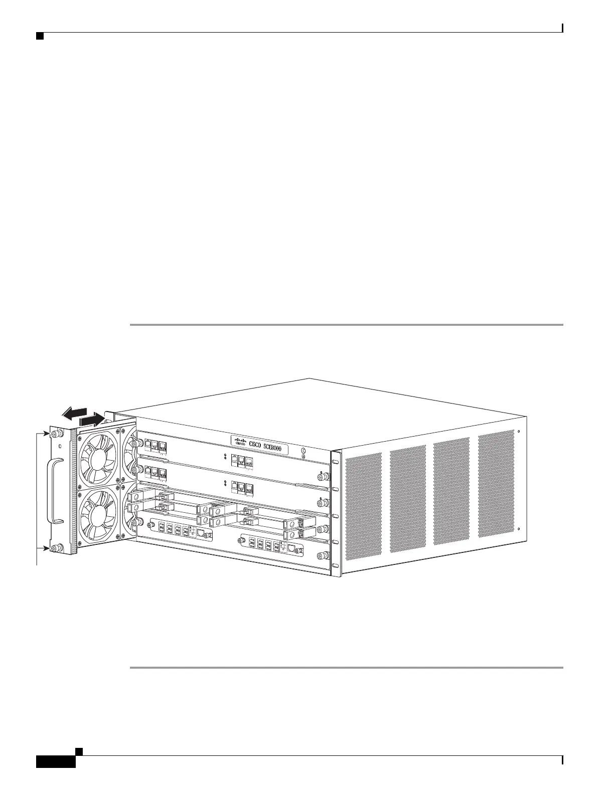
Step 1 Loosen the two captive installation screws (Figure 9-7) by turning them counterclockwise.
Figure 9-7 Fan Assembly
When removing the fan tray, keep your hands and fingers away from the spinning fan blades. Let the fan
blades completely stop before you remove the fan tray.
Step 2 Grasp the fan assembly with both hands and pull it outward; rock it gently if necessary to unseat the
power connector from the backplane.
Step 3 Pull the fan assembly clear of the chassis, and put it in a safe place.
270893
S
YS
T
E
M
P
OWE
R
OPTI
C
AL BY
P
ASS
STATUS
A
U
X
P
O
R
T
2
LI
N
K
AC
T
I
VE
M
AS
T
E
R
SC
E8
0
0
0
E
X
T
E
N
D
ED
S
ER
VICE CO
N
T
ROL
M
O
DUL
E
O
P
T
I
C
A
L
B
Y
P
A
S
S
O
P
T
I
C
A
L
B
Y
P
A
S
S
C
O
N
S
O
L
E
1
0
1
0
0
1
0
0
0
LI
N
K
AC
T
I
VE
P
O
R
T
1
A
C
A
B
C
D
B
D
S
TATUS
C
T
R
L
O
P
B
-
SC
E
8
K
-
M
M
O
PT
IC
A
L
B
YPA
SS1
TX
R
X
TX
R
X
TX
RX
TX
RX
A
C
A
B
C
D
B
D
ST
A
TUS
CTR
L
O
P
B
-
S
C
E
8
K
-
M
M
O
P
T
I
C
A
L
BY
P
AS
S
2
T
X
RX
T
X
RX
T
X
RX
T
X
RX
S
Y
S
T
E
M
POWE
R
OP
T
I
C
AL BY
P
ASS
STATUS
A
U
X
P
O
RT 2
1
0
1
0
0
1
0
0
0
L
I
N
K
A
CT
I
V
E
M
A
STER
SC
E8
0
0
0
E
X
T
E
N
D
ED
S
ERVI
C
E CON
T
R
O
L
M
O
D
UL
E
S
C
E
8
0
0
0
-
S
C
M
-
E
S
C
E
8
0
0
0
-
S
C
M
-
E
S
C
E
8
0
0
0
-
S
I
P
C
O
N
S
O
L
E
1
0
1
0
0
1
0
0
0
L
I
N
K
A
C
T
I
V
E
P
O
R
T
1
O
P
T
I
C
A
L
B
Y
P
A
S
S
O
P
T
I
C
A
L
B
YP
AS
S
STA
TU
S
ACTIVE/L
I
N
K
S
P
A
-
1
X1
0
G
E-
L
-
V
2
ST
A
TU
S
A
CTI
VE/L
I
NK
S
PA
-
1
X1
0
G
E
-
L
-
V
2
ST
A
T
U
S
ACTI
VE
/
L
I
N
K
S
P
A
-
1
X10
G
E
-
L
-
V
2
ST
A
TU
S
ACT
I
VE/
L
I
N
K
S
PA-
1
X
10
G
E
-
L
-
V
2
1
0
10
0
1
0
0
0
F
A
N
S
T
A
T
U
S
Captive installation screws