2-13
Cisco SCE8000 GBE Installation and Configuration Guide
OL-19897-02
Chapter 2 Introduction to the Cisco SCE8000 GBE Platform
The Cisco SCE8000 GBE Optical Bypass
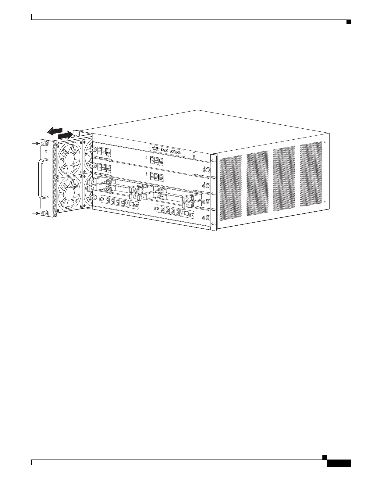
Fan Assembly
The system fan assembly, located in the chassis, provides cooling air for the installed modules
(Figure 2-8). Sensors on the fan assembly and within the system monitor the internal air temperatures.
If the air temperature exceeds a preset threshold, the environmental monitor displays warning messages.
Figure 2-8 Fan Assembly
If an individual fan within the assembly fails, the FAN STATUS LED turns red. To replace a fan
assembly, see Removing and Replacing the Fan Assembly, page 9-12.
Power Supplies
The Cisco SCE8000 GBE platform supports redundant AC- or DC-input power supplies. The following
power supplies are available for the Cisco SCE8000 GBE platform:
• 2700 W DC input (PWR-2700-DC/4): uses an external terminal block on the back side of the chassis
for input power connection (Figure 2-10).
• 2700 W AC input (PWR-2700-AC/4): uses an external power cord directly connected to the AC
power supply (Figure 2-9).
270893
S
YS
T
E
M
POWE
R
OP
T
I
C
A
L
BYPASS
S
TATUS
A
U
X
P
O
R
T
2
LI
N
K
AC
T
I
VE
MAST
E
R
SC
E8
0
0
0
E
X
T
E
N
D
ED
S
ER
VICE CO
N
T
R
O
L
MODULE
O
P
T
I
C
A
L
B
Y
P
A
S
S
O
P
T
IC
A
L
B
Y
P
A
S
S
C
O
N
S
O
L
E
1
0
1
0
0
1
0
0
0
LI
N
K
AC
T
I
VE
P
O
R
T
1
A
C
A
B
C
D
B
D
S
TATUS
CTR
L
OP
B
-SC
E
8
K
-M
M
OPTIC
AL
BYPA
SS1
TX
R
X
TX
R
X
TX
RX
TX
RX
A
C
A
B
C
D
B
D
ST
A
TUS
CTR
L
O
P
B
-
S
C
E
8
K
-
M
M
O
P
T
I
C
A
L
BY
P
AS
S
2
T
X
RX
T
X
RX
T
X
RX
T
X
RX
S
Y
S
T
E
M
POWE
R
OP
T
I
C
AL BY
P
ASS
STATUS
A
U
X
P
O
RT 2
1
0
10
0
1
0
0
0
L
I
N
K
A
CT
I
V
E
M
A
STER
SC
E8
0
0
0
E
X
T
E
N
D
ED
S
ERVIC
E CON
T
R
O
L
M
O
D
UL
E
S
C
E
8
0
0
0
-
S
C
M
-
E
S
C
E
8
0
0
0
-
S
C
M
-
E
S
C
E
8
0
0
0
-
S
I
P
C
O
N
S
O
L
E
1
0
1
0
0
1
0
0
0
L
I
N
K
A
C
T
I
V
E
P
O
R
T
1
O
P
T
I
C
A
L
B
Y
P
A
S
S
O
P
T
I
C
A
L
B
YP
AS
S
STA
TU
S
ACTIVE/L
I
N
K
S
PA
-
1
X1
0
G
E-
L
-
V
2
ST
A
TU
S
A
CT
I
VE/
L
I
NK
S
P
A
-
1
X1
0
G
E
-
L-
V
2
ST
A
T
U
S
ACTI
VE
/
L
I
N
K
S
P
A
-
1
X10
G
E
-
L
-
V
2
ST
A
TU
S
ACT
I
VE/
L
I
N
K
S
P
A
-
1
X
10
G
E
-
L
-
V
2
1
0
10
0
1
0
0
0
F
A
N
S
T
A
T
U
S
Captive installation screws