3-3
Cisco SCE8000 GBE Installation and Configuration Guide
OL-19897-02
Chapter 3 Cisco SCE8000 GBE Topology and Topology-Related Parameters
Physical Topologies
These issues determine two important aspects of system deployment and configuration:
• Physical topology of the system — The actual physical placement and connection of the Cisco
SCE8000 GBE platform or platforms in the system.
• Topology-related configuration parameters — The correct values for each parameter must be
ascertained before configuring the system to make sure that the system will function in the desired
manner.
Physical Topologies
Following are descriptions of a number of physical topologies that the Cisco SCE8000 GBE supports.
• SCE8000 GBE Interface Numbering, page 3-3
• Single Cisco SCE8000 GBE Topologies, page 3-4
• Dual Cisco SCE8000 GBE Topology (Cascade), page 3-5
SCE8000 GBE Interface Numbering
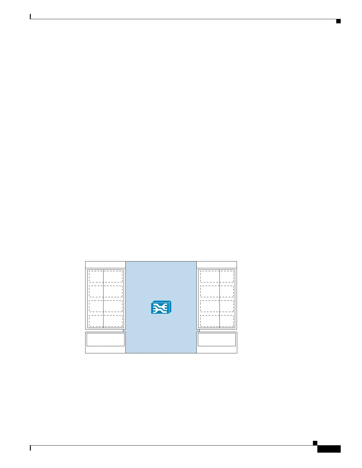
Figure 3-1 shows the numbering of the SCE8000 GBE interfaces as indicated in the topology diagrams
in this chapter. The interface numbering is explained as follows:
• The first digit is the slot number (always 3).
• The second digit is the number of the sub-slot or SPA module (0-3).
• The third digit is the number of the interface on the designated SPA module (0 to 7).
Figure 3-1 SCE8000 GBE Interface Numbering
275782
SCE8000 GBE
Traffic GBE SPA 1
1/0–S
1/1–N
L4
1/2–S
1/3–N
L5
1/4–S
1/5–N
L6
1/6–S
1/7–N
L7
0/0–S
0/1–N
L0
0/2–S
0/3–N
L1
0/4–S
0/5–N
L2
0/6–S
0/7–N
L3
Cascade 10GBE
SPA 3
3/0-cascade
Traffic GBE SPA 0
Cascade 10GBE
SPA 2
2/0-cascade