6-8
Cisco SCE8000 GBE Installation and Configuration Guide
OL-19897-02
Chapter 6 Cabling the GBE Line Ports and Completing the Installation
Cabling the GBE Line Interface Ports
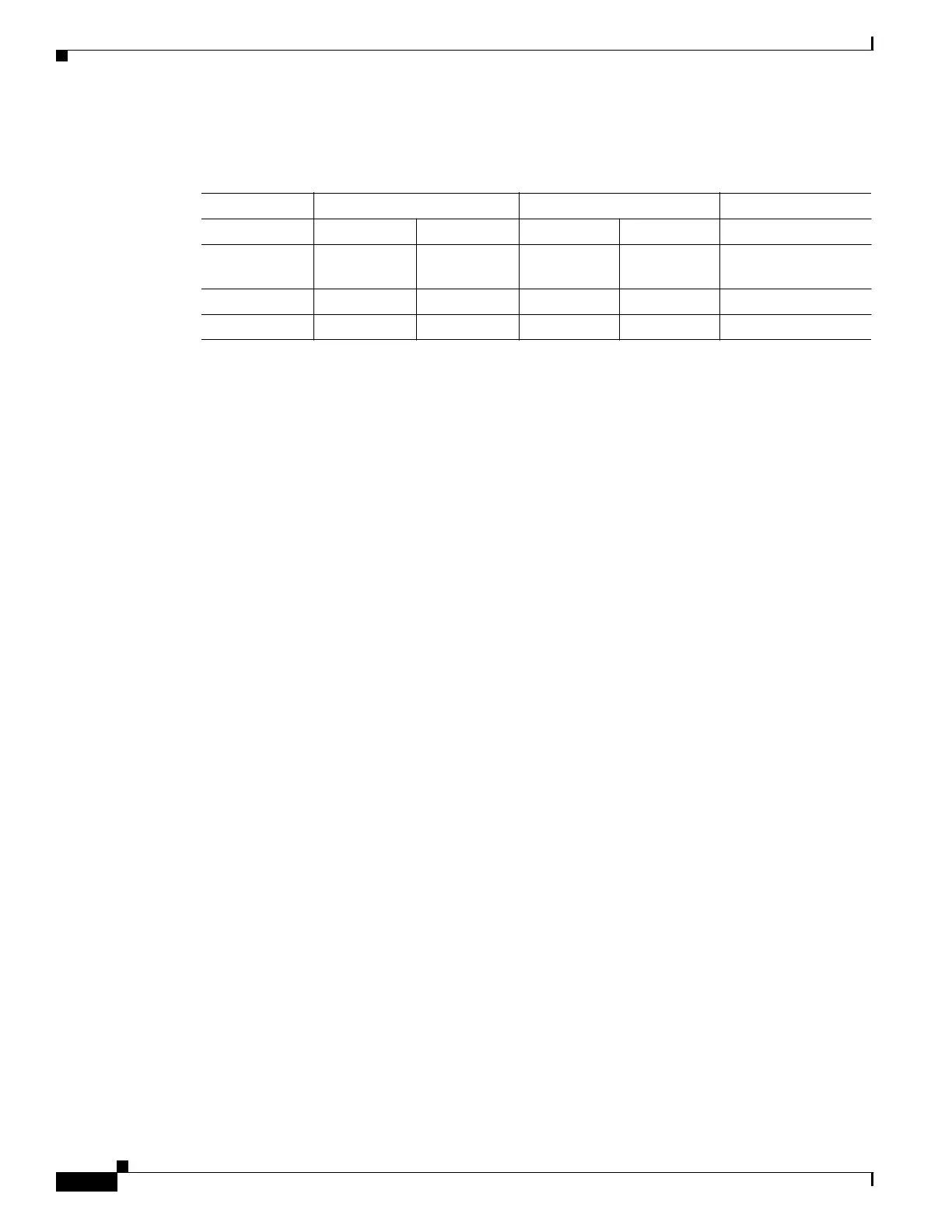
Table 6-4 provides power information and specifications.
1
For fiber types 9/125 mm SMF.
2
For fiber types 62.5/125 mm MMF and 50/125 mm MMF.
3
For fiber types 9/125 mm SMF, 62.5/125 mm MMF, and 50/125 mm MMF.
4
For fiber types 50/125 mm MMF and 62.5/125 mm MMF.
5
For fiber type 10 mm SMF.
6
For fiber types 50/125 mm, NA = 0.20 fiber and 62.5/125 mm, NA = 0.275 fiber.
7
For fiber types 50/125 mm MMF and 62.5/125 mm MMF.
Optical Device Maintenance
Any contamination of the fiber connection can cause failure of the component or failure of the whole
system. A particle that partially or completely blocks the core generates strong back reflections, which
can cause instability in the laser system. Inspection, cleaning, and reinspection are critical steps to take
before making fiber-optic connections.
Table 6-4 SFP-GE-L, SFP-GE-S, and SFP-GE-Z Module Power Specifications
SFP Module Transmit Power (dBm) Receive Power (dBm) Power Budget (dBm)
Minimum Maximum Minimum Maximum
SFP-GE-L -9.5
1
-11.5
2
-3 .0
3
-19.0 -3.0 7.5
4
and 9.5
5
SFP-GE-S 9.5
6
-3.0 -17.0 0.0 7.5
7
SFP-GE-Z 0.0 5.0 -22.0 0.0 22