3-4
Cisco SCE8000 GBE Installation and Configuration Guide
OL-19897-02
Chapter 3 Cisco SCE8000 GBE Topology and Topology-Related Parameters
Physical Topologies
Single Cisco SCE8000 GBE Topologies
• Inline vs. Receive-only Installation, page 3-4
A single Cisco SCE8000 GBE supports a number of different topologies, depending on the number of
SPAs and the connection mode.
The number of traffic links per number of SPAs is listed in Table 3-1.
Inline vs. Receive-only Installation
Inline Topology
Typically, the Cisco SCE8000 GBE is connected in a full duplex link between two devices (Router,
BRAS, etc.). When the Cisco SCE8000 GBE is installed as an inline installation, it physically resides
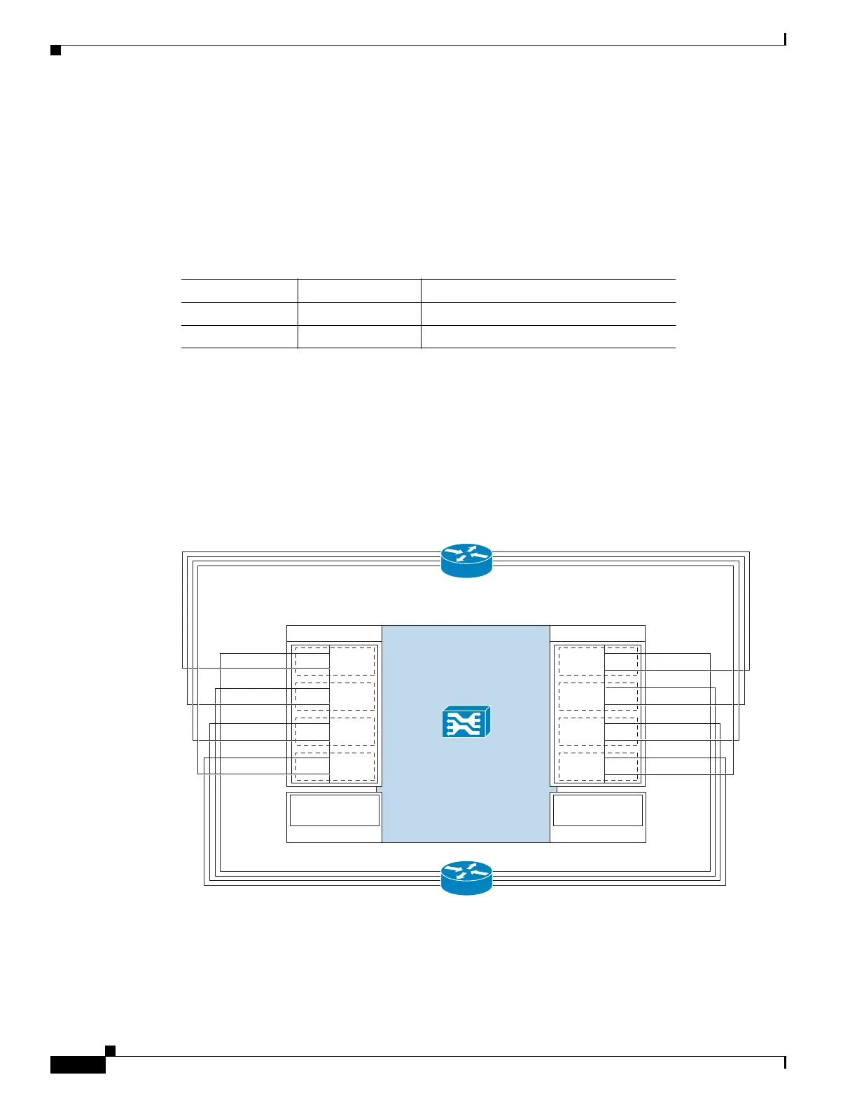
on the data link between the subscribers and the network. Figure 3-2 displays the inline topology.
Figure 3-2 Inline Topology
When configuring the Cisco SCE8000 GBE , an inline installation is referred to as “inline” connection
mode.
Table 3-1 Number of SPAs
Number of SPAs Number of Links Place SPAs in subslots...
14 0
2 8 0 and 1
275783
SCE8000 GBE
Traffic GBE SPA 1
1/0–S
1/1–N
L4
1/2–S
1/3–N
L5
1/4–S
1/5–N
L6
1/6–S
1/7–N
L7
0/0–S
0/1–N
L0
0/2–S
0/3–N
L1
0/4–S
0/5–N
L2
0/6–S
0/7–N
L3
Cascade 10GBE
SPA 3
3/0-cascade
Traffic GBE SPA 0
Cascade 10GBE
SPA 2
2/0-cascade
Network side
(upstream)
Subscriber side
(downstream)