4-11
Cisco SCE8000 GBE Installation and Configuration Guide
OL-19897-02
Chapter 4 Installing the Cisco SCE8000 GBE Chassis
Preparing for Installation
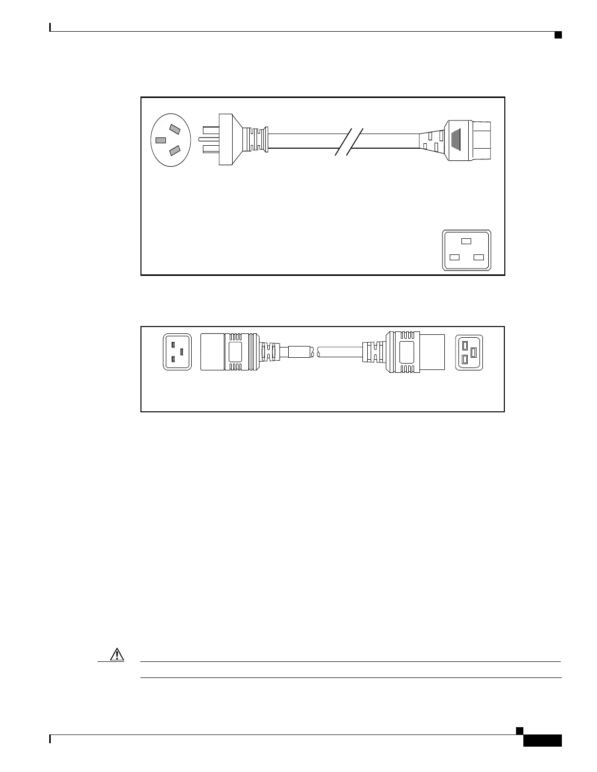
Figure 4-11 CAB-AC-16A-AUS
Figure 4-12 CAB-C19-CBN
DC-Powered Systems
Basic guidelines for DC-powered systems include the following:
• Each chassis power supply should have its own dedicated input power source. The source must
comply with the safety extra-low voltage (SELV) requirements in the UL 60950, CSA 60950, EN
60950, IEC 60950 standards.
• The DC supplies each have the provision for a dual connection to the power source in order to permit
high-power operation without exceeding current ratings. For the SCE8000 GBE , it is not necessary
to connect both of these inputs to DC power sources; it is sufficient to connect only the '1'
connections.
• Each circuit must be protected by a dedicated two-pole circuit breaker. The circuit breaker should
be sized according to the power supply input rating and local or national code requirements.
• The circuit breaker is considered the disconnect device and should be easily accessible.
• The system ground is the power supply and chassis ground.
Caution Do not connect the DC-return wire to the system frame or to the system grounding equipment.
Cordset rating: 16 A, 250 V
Length: 14 ft 0 in. (4.26 m)
140586
Connector: IEC 60320 C19
Plug: AU20S3
Cordset rating: 16 A, 250 V
Length: 9 ft 0 in. (2.7 m)
140587
Connector:
IEC 60320 C19
Connector:
IEC 60320 C20