2-3
Cisco SCE8000 GBE Installation and Configuration Guide
OL-19897-02
Chapter 2 Introduction to the Cisco SCE8000 GBE Platform
Service Control Module (SCE8000-SCM-E)
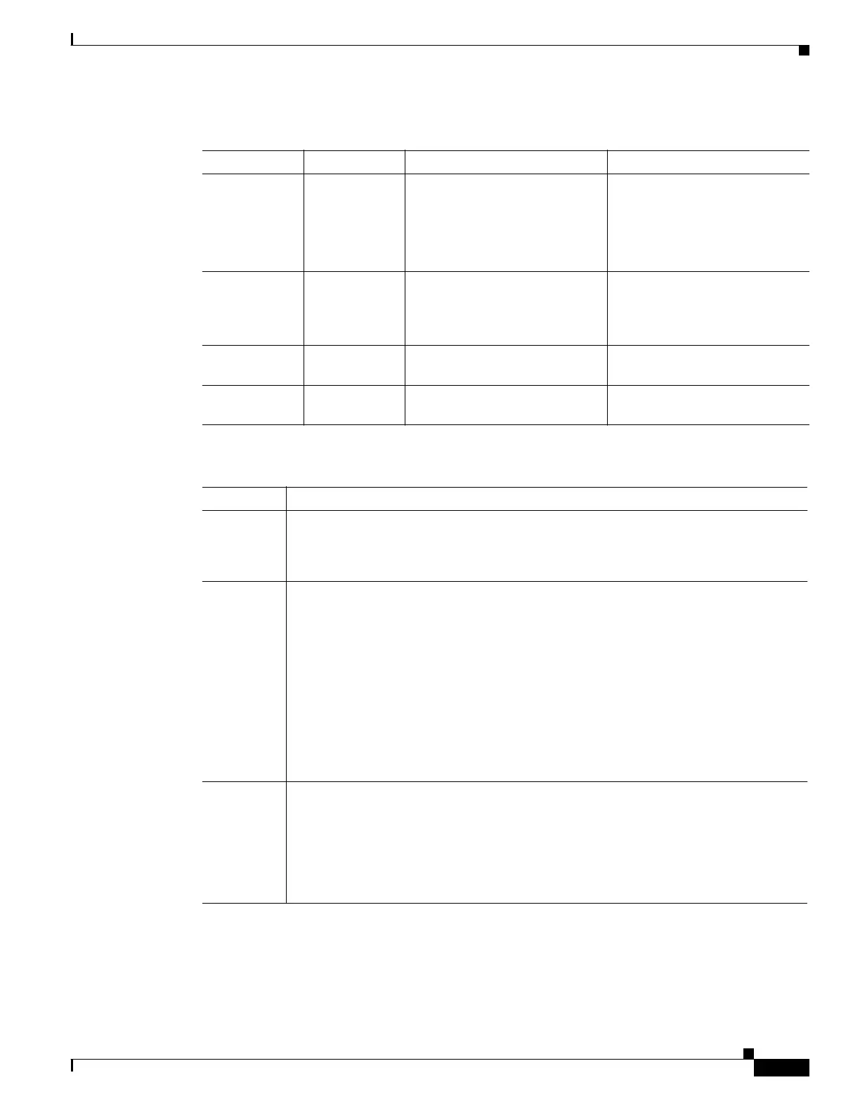
Table 2-2 SCE8000-SCM-E Ports
Port Quantity Description Connect This Port To…
GBE port 2
Currently only
one GBE port
is supported.
Gigabit Ethernet RJ-45 ports for
management of the Cisco
SCE8000 GBE .
CLI designation: interface
GigabitEthernet 1/1, 1/2.
A LAN using a GBE cable with
an RJ-45 connector.
Console 1 RS-232 RJ-45 port for use by
technicians
A local terminal (console) using
an RS-232 cable with an RJ-45
connector, as provided in the
Cisco SCE8000 GBE kit.
AUX 1 RS-232 RJ-45 port used by
technicians
Bypass 2 RJ-11 port The Control connector on the
optical bypass module.
Table 2-3 SCE8000-SCM-E LEDs
LEDs Description
Power
• Steady green — Installed power supplies are functioning normally.
• Steady amber — Only one power supply is functioning normally.
• Unlit — No power from either power supply.
Status The Status LED indicates the operational status of the Cisco SCE8000 GBE system, as
follows:
• Unlit — No power from either power unit.
• Steady amber — The system is booting up.
• Flashing amber — The system is operational, but is in a warning state.
• Flashing green — The system is fully operational.
• Steady red — There is a problem or failure
Note that Alarms are hierarchical: Failure takes precedence over Warning, which takes
precedence over Operational.
Optical
Bypass
• Steady amber — The optic bypass module has been directed to pass traffic via the
Cisco SCE8000 GBE.
• Unlit — The optic bypass module (if present) will connect the link fibers directly,
and traffic will bypass the Cisco SCE8000 GBE.
Note that this functionality is consistent even when the Cisco SCE8000 GBE is powered
down.