DeviceMaster Installation and Configuration Guide: 2000594 Rev. F Hardware Installation - 17
Hardware Installation
5. Go to Initial Configuration on Page 33 to configure the DeviceMaster for use.
DM-2101: 1-Port DIN Rail (DB9) Installation
Use the following procedure to install a DM-2101.
1. Attach the DM-2101 to the DIN rail adapter.
2. Connect the power supply and apply power to the DM-2101 using the power supply specifications on the
product label and the following information.
Observe proper ESD techniques when connecting and disconnecting the DeviceMaster.
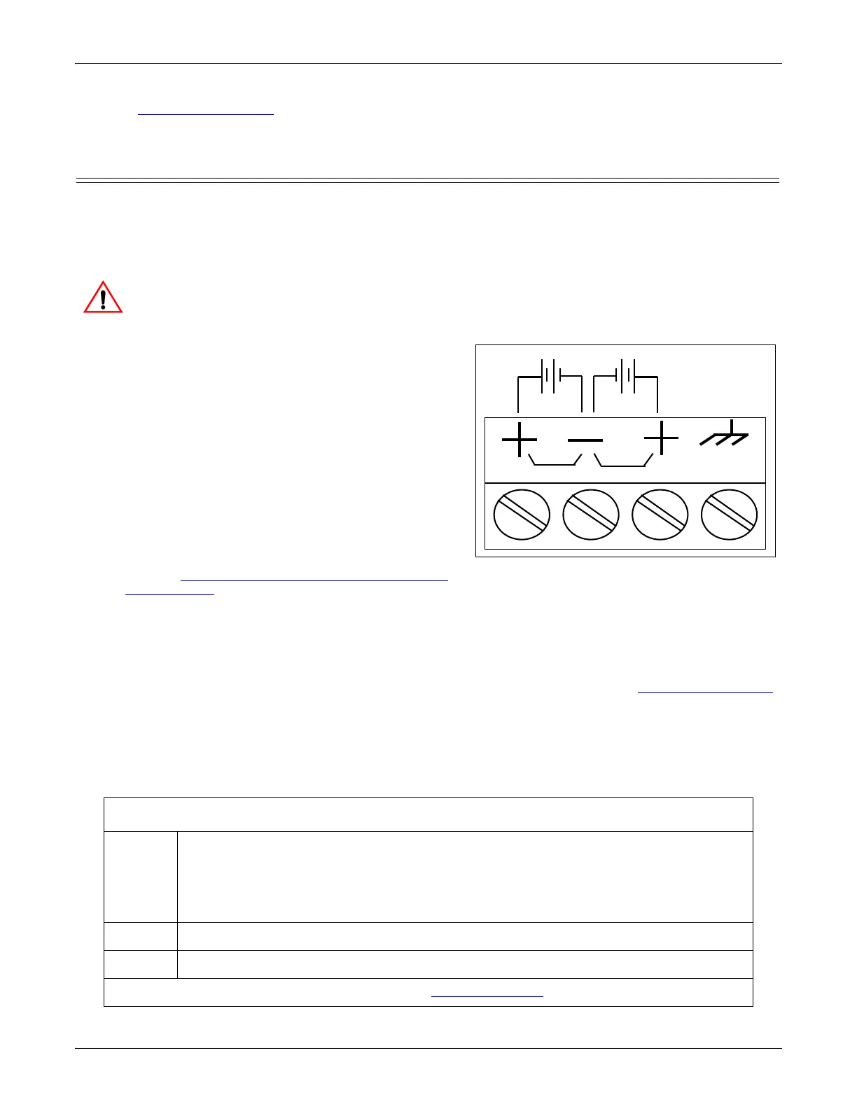
a. If the DIN rail is not connected to earth ground,
insert the earth ground wire into the chassis ground
screw terminal.
Note: The chassis ground connection is made only if the
DIN rail is NOT connected to earth ground.
b. Insert the DC positive wire into one of the + screw
terminals and the DC return wire into the - screw
terminal.
• A second redundant power supply can be
connected to the unit by inserting the DC
positive wire into the other + screw terminal and
the DC return wire into the - screw terminal.
• The DM-2101 continues to operate if one of the
two connected power supplies should fail.
Refer to DM-2101 and DM-2201: 1-Port DIN Rail
Power Supply on Page 140 for detailed power
requirements.
c. Use a small flat head screw driver to lock the wires into place.
d. Verify that each wire has been tightened securely.
e. Connect a UL Listed power supply and UL Listed power cord to a power source to apply power.
Note: Do not connect multiple units until you have changed the default IP address, see Initial Configuration
on Page 33.
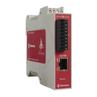
3. Connect the 10/100 port to the same Ethernet network segment as the host PC using a standard Ethernet
cable.
4. Verify that the Status LED has completed the boot cycle and network connection for the DM-2101 is
functioning properly using the following table.
DM-2101 LED Descriptions
STATUS
The STATUS LED on the device is lit, indicating you have power and it has completed
the boot cycle.
Note: The Status LED flashes while booting and it takes approximately 15 seconds for
the Bootloader to complete the cycle. When the Bootloader completes the cycle,
the LED has a solid, steady light that blinks approximately every 10 seconds.
LINK If the LINK (green) LED is lit, it indicates a working Ethernet connection.
ACT If the ACT (yellow) LED flashes, it indicates network activity.
Note: For additional LED information, go to the Status LED table on Page 148.
† Wire gauge: AWG 12-22
PW1
PW2
Chassis
Ground†
Return†
Positive†Positive†
5-30VDC 5-30VDC