88 - Connecting Serial Devices DeviceMaster Installation and Configuration Guide: 2000594 Rev. F
Connecting Serial Devices
DB9 Connectors
This subsection provides the following information:
• Connector pin assignments (below)
• DB9 Null-Modem Cables (RS-232) on Page 89
• DB9 Null-Modem Cables (RS-422) on Page 89
• DB9 Straight-Through Cables (RS-232/485) on Page 89
• DB9 Loopback Plugs on Page 90
• Connecting DB9 Serial Devices on Page 90
Note: The DeviceMaster Serial Hub only supports RS-232.
Refer to the hardware manufacturer’s installation documentation if you need help with connector pin outs or
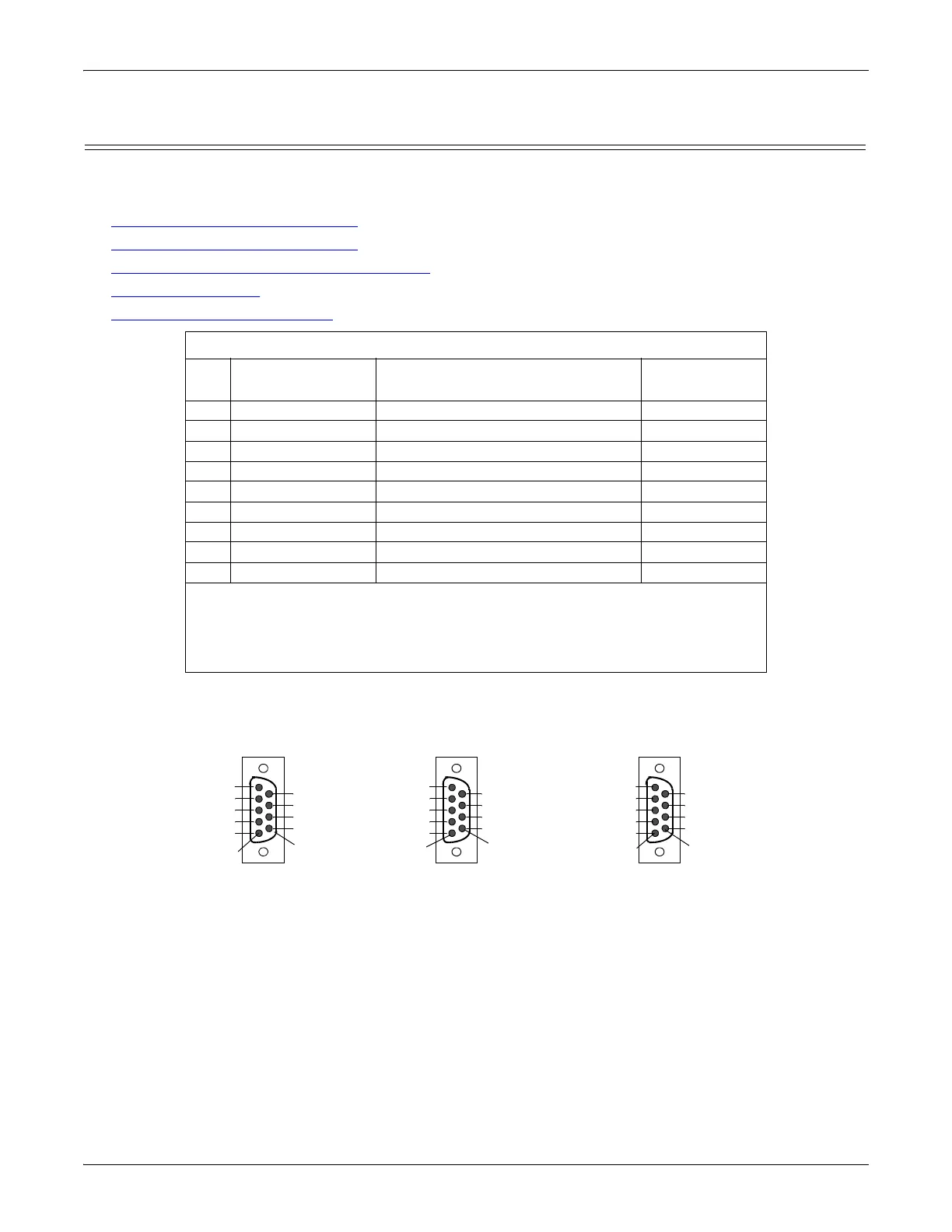
cabling for the serial device. This illustrates the DB9 connector signals.
DB9 Connector Pin Outs
Pin RS-232
RS-422 and RS-485 Full-Duplex
(Master/Slave)†
RS-485
Half-Duplex
1 DCD Not used Not used
2RxD RxD- Not used
3 TxD TxD- TRxD-
4 DTR Not used Not used
5 Signal GND Signal GND Signal GND
6 DSR Not used Not used
7 RTS TxD+ TRxD+
8CTS RxD+ Not used
9 RI Not used Not Used
† The following models support RS-485 full-duplex:
• 1-Port DIN rail models
• 2-Port DIN rail models
• 4-Port DIN rail models
Pin 1
Pin 6
DB9 Male
RS-232
RI
CTS
RTS
DSR
GND
DTR
TxD
RxD
CD
Pin 1
Pin 6
DB9 Male
RS-422
Not used
RxD+
TxD+
Not used
GND
Not used
TxD-
RxD-
Not used
Pin 1
Pin 6
DB9 Male
RS-485
Not used
Not used
TRxD+
Not used
GND
Not used
TRxD-
Not used
Not used