DeviceMaster Installation and Configuration Guide: 2000594 Rev. F Hardware Installation - 21
Hardware Installation
3. Use the appropriate method for network attachment of your DeviceMaster 2-port:
• DM-2102: Connect the 10/100 port to the same Ethernet network segment as the host PC using a
standard network cable.
• DM-2302: Connect either 10/100 port to the same Ethernet network segment as the host PC using a
standard network cable. You can daisy-chain another DeviceMaster or Ethernet device to the other
Ethernet port.
4. Verify that the Status LED has completed the boot cycle and network connection for the DeviceMaster is
functioning using the following table.
Do not connect RS-422/485 devices until the IP address is configured and an appropriate
port interface type has been configured. The default port setting is RS-232.
5. Go to Initial Configuration on Page 33 to configure the DeviceMaster for use.
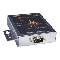
DM-2102 and DM-2302
(2-Port with DB9 Connectors) LED Descriptions
STATUS
The STATUS LED on the device is lit, indicating you have power and it has completed the
boot cycle.
Note: The Status LED flashes while booting and it takes approximately 15 seconds for
the Bootloader to complete the cycle. When the Bootloader completes the cycle, the
LED has a solid, steady light that blinks approximately every 10 seconds.
LINK If the LINK (green) LED is lit, it indicates a working Ethernet connection.
ACT If the ACT (yellow) LED flashes, it indicates network activity.
Note: For additional LED information, go to the Status LED table on Page 148.