130BC517.11
250
[9.8]
844
[33.2]
889
[35.0]
909
[35.8]
130
[5.1]
656
[25.8]
200
[7.9]
180
[7.1]
495
[19.5]
660
[26.0]
61
[2.4]
148
[5.8]
82
[3.2]
18
[0.7]
375
[14.8]
20
[0.8]
200
[7.9]
77.5
[3.1]
122.5
[4.8]
26
[1.0]
844
[33.2]
128
[5.0]
1
4
2
3
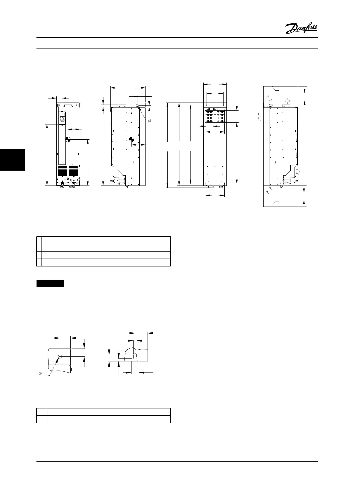
Figure 6.11 Mechanical Dimensions, D3h
1
Ceiling
2 Air space outlet minimum 225 mm [8.9 in]
3 Air space inlet minimum 225 mm [8.9 in]
4 Floor
Table 6.5 Legend to Figure 6.11
NOTICE!
If using a kit to direct the airflow from the heatsink to
the outside vent on the back of the adjustable frequency
drive, the required ceiling clearance is 4 in [100 mm].
1 2
33
[1.3]
25
[1.0]
24
[0.9]
20
[0.8]
40
[1.6]
11
[0.4]
9
[0.3]
11
[0.4]
130BD517.10
Figure 6.12 Detail Dimensions, D3h
1 Top mounting hole detail
2 Bottom mounting slot detail
Table 6.6
Mechanical Installation Design Guide
114 Danfoss A/S © Rev. 2014-02-10 All rights reserved. MG34S222
66

 Loading...


