130BD463.10
149
[5.9]
731
[28.8]
1107
[43.6]
381
[15]
115
[4.5]
23
[0.9]
16.1
[6.3]
1277
[50.3]
123
[4.8]
1324
[52.1]
1276
[50.2]
200
[7.9]
78
[3.1]
123
[4.8]
78
[3.1]
200
[7.9]
220
[8.7]
130
[5.1]
200
[7.9]
1111
[43.7]
130
[5.1]
325
[12.8]
306
[12.1]
276
[10.9]
180
[7.1]
2
1
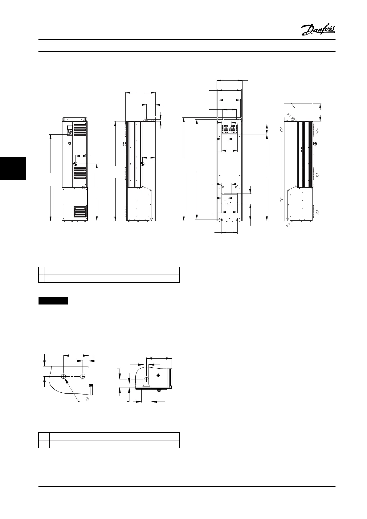
Figure 6.15 Mechanical Dimensions, D5h
1
Ceiling
2 Air space outlet minimum 225 mm [8.9 in]
Table 6.9 Legend to Figure 6.15
NOTICE!
If using a kit to direct the airflow from the heatsink to
the outside vent on the back of the adjustable frequency
drive, the required ceiling clearance is 4 in [100 mm].
64
[2.5]
63
[2.5]
24
[0.9]
9
[0.3]
25
[1.0]
11
[0.4]
20
[0.8]
15
[0.6]
11
[0.4]
4X
1 2
130BD518.10
Figure 6.16 Detail Dimensions, D5h
1 Top mounting hole detail
2 Bottom mounting slot detail
Table 6.10 Legend to Figure 6.16
Mechanical Installation Design Guide
116 Danfoss A/S © Rev. 2014-02-10 All rights reserved. MG34S222
66
 Loading...


