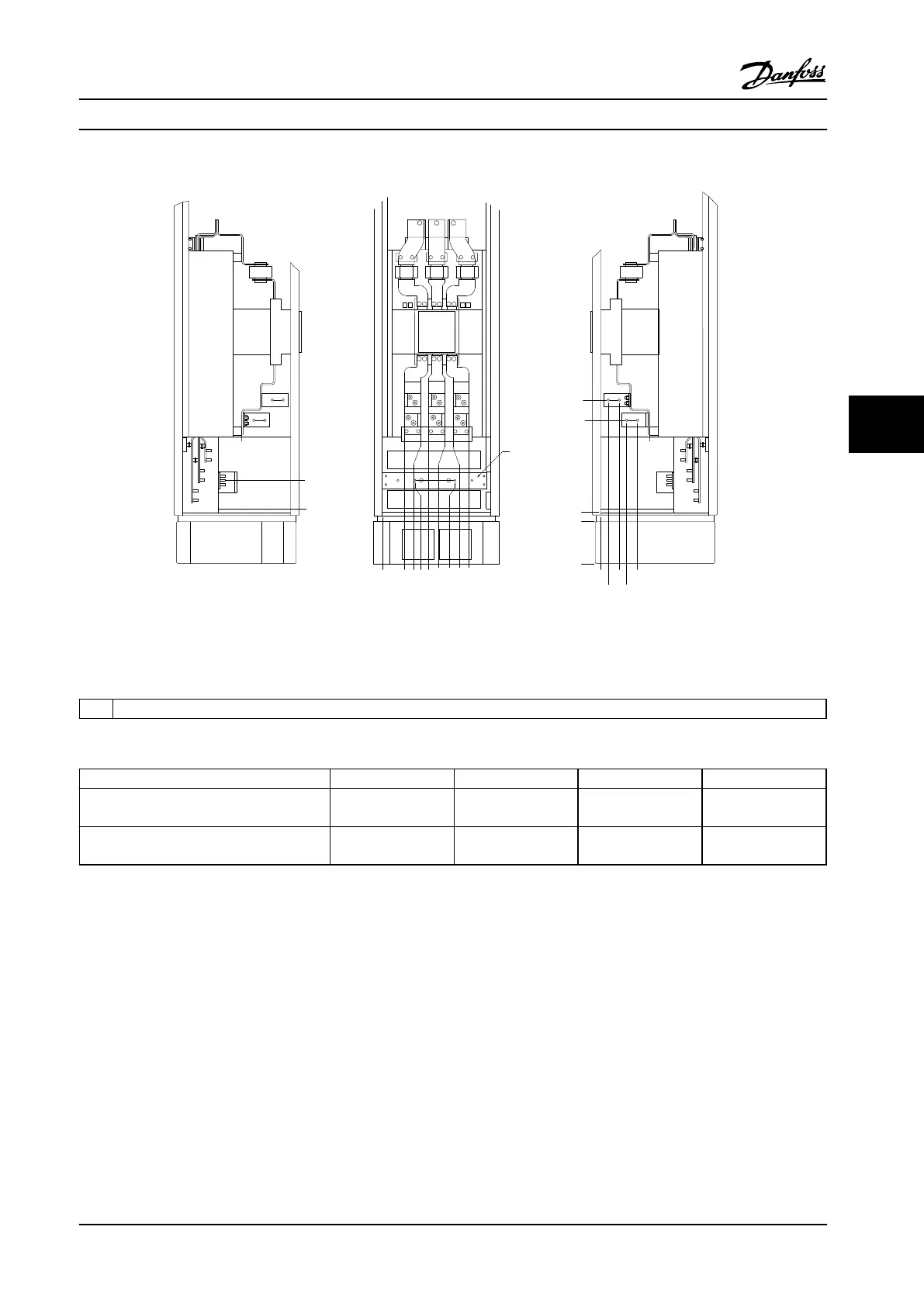
Terminal Locations - Options Cabinet with Circuit Breaker/Molded Case Switch (F3 and F4)
0.0 [0.00]
134.6 [5.30]
104.3 [4.11]
0.0 [0.00]
179.3 [7.06]
219.6 [8.65]
294.6 [11.60]
334.8 [13.18]
409.8 [16.14]
436.9 [17.20]
0.0 [0.00]
532.9 [20.98]
0.0 [0.00]
44.4 [1.75]
244.4 [9.62]
154.0 [6.06]
344.0 [13.54]
1
2
3
4
5
130BA852.11
Figure 6.73 Terminal Locations - Options Cabinet with Circuit Breaker/Molded Case Switch (Left, Front and Right Side View).
Connector Plate is 1.65 in [42 mm] below .0 Level.
1
Ground bar
Table 6.39 Legend to Figure 6.73
Power size 2 3 4 5
600 hp [450 kW] (480 V), 850–950 hp
[630–710 kW] (690 V)
34.9 86.9 122.2 174.2
650–1075 hp [500–800 kW] (480 V),
1075–1350 hp [800–1000 kW] (690 V)
46.3 98.3 119.0 171.0
Table 6.40 Dimension for Terminal
Mechanical Installation Design Guide
MG34S222 Danfoss A/S © Rev. 2014-02-10 All rights reserved. 157
6 6

 Loading...


