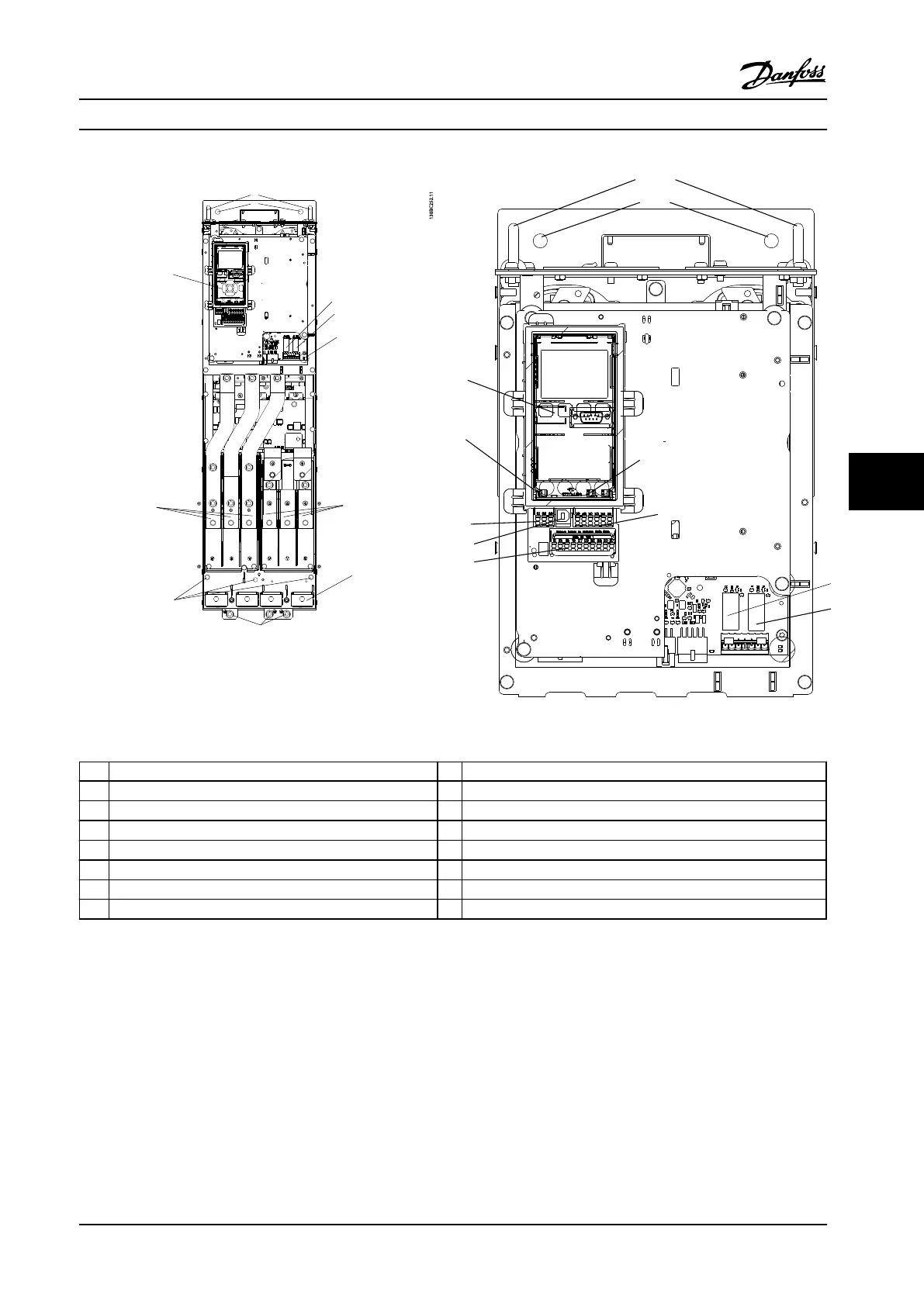
D-frame Interior Components
130BC252.11
1
15
14
8
9
12
13 (IP 20/Chassis)
13
(IP 21/54
NEMA 1/12)
11
10
16
Figure 7.3 D-frame Interior Components
Figure 7.4 Close-up View: LCP and Control Functions
1
LCP (Local Control Panel) 9 Relay 2 (04, 05, 06)
2 RS-485 serial bus connector 10 Lifting ring
3 Digital I/O and 24 V power supply 11 Mounting slot
4 Analog I/O connector 12 Cable clamp (PE)
5 USB connector 13 Ground
6 Serial bus terminal switch 14 Motor output terminals 96 (U), 97 (V), 98 (W)
7 Analog switches (A53), (A54) 15 Line power input terminals 91 (L1), 92 (L2), 93 (L3)
8 Relay 1 (01, 02, 03)
Table 7.3 Legend to Figure 7.3 and Figure 7.4
Electrical Installation
Design Guide
MG34S222 Danfoss A/S © Rev. 2014-02-10 All rights reserved. 181
7 7

 Loading...


