NOTICE!
The power cables are heavy and difficult to bend. Consider the optimum position of the adjustable frequency drive to
ensure easy cable installation. Each terminal allows use of up to four cables with cable lugs or use of standard box lug.
Ground is connected to a relevant termination point in the adjustable frequency drive.
104[4.1]
35[1.4]
10[0.4]
0[0.0]
0[0.0]
40[1.6]
78[3.1]
0[0.0]
26[1.0]
26[1.0]
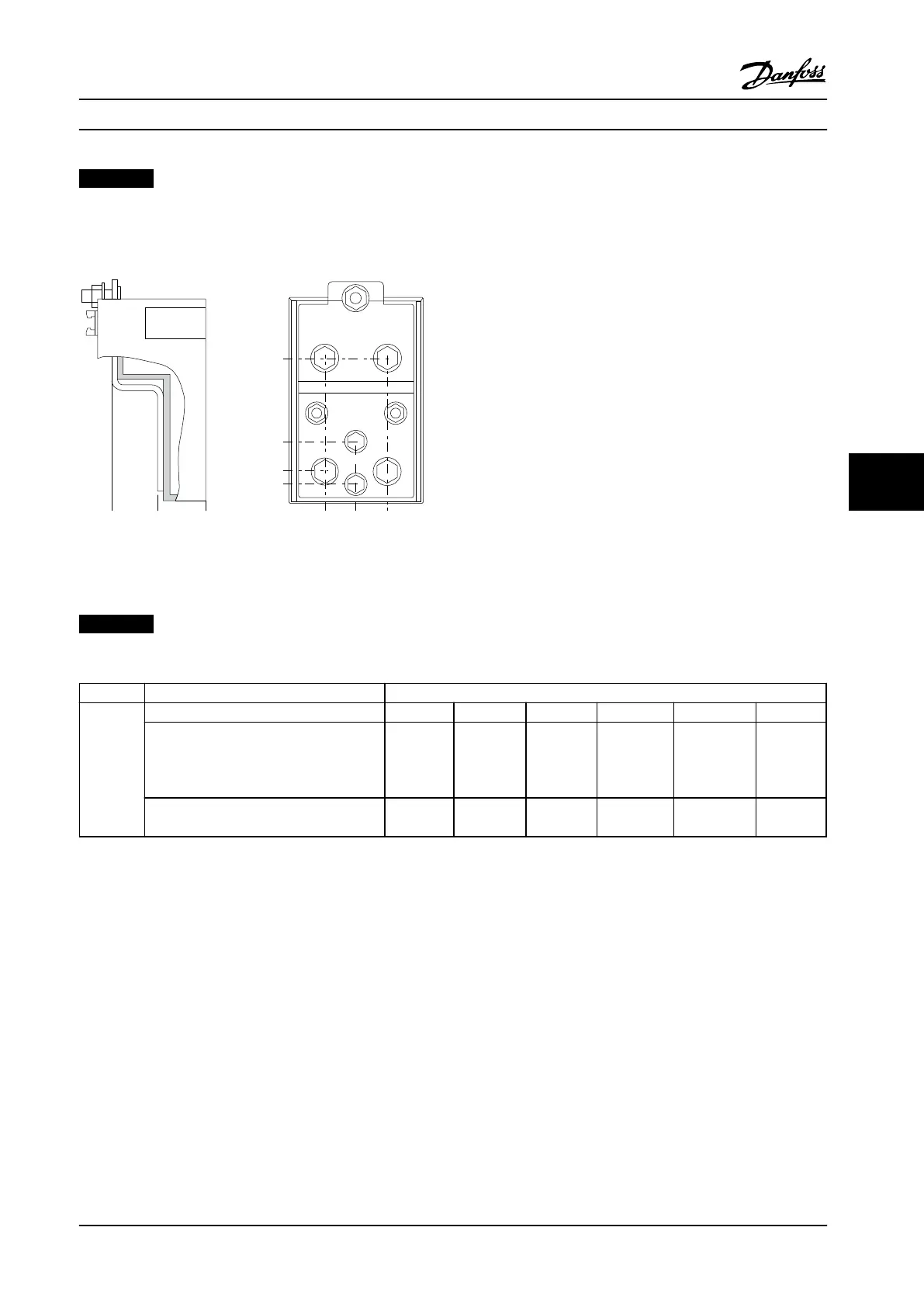
176FA271.10
Figure 7.23 Terminal in Detail
NOTICE!
Power connections can be made to positions A or B.
Frame size Unit type Dimension for disconnect terminal
E2
A B C D E F
350/450 hp [250/315 kW] (400 V) and
475/600–650/850 hp
[355/450–500/630 KW]
(690 V)
381 (15.0) 245 (9.6) 334 (13.1) 423 (16.7) 256 (10.1) N/A
450/475–550/600 hp [315/355-400/450 kW]
(400 V)
383 (15.1) 244 (9.6) 334 (13.1) 424 (16.7) 109 (4.3) 149 (5.8)
Table 7.17 Power Connections, E2
Electrical Installation Design Guide
MG34S222 Danfoss A/S © Rev. 2014-02-10 All rights reserved. 199
7 7

 Loading...


