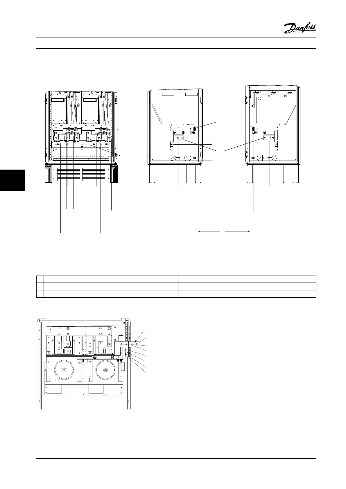
Terminal Locations - Frame Sizes F1 and F3
Take the following position of the terminals into consideration when designing the cable access.
130BA849.13
.0 [.0]
54.4[2.1]
169.4 [6.7]
284.4 [11.2]
407.3 [16.0]
522.3 [20.6]
637.3 [25.1]
287.4 [11.3]
253.1 [10.0]
.0 [.0]
.0 [.0]
339.4 [13.4]
287.4 [11.3]
.0 [.0]
339.4 [13.4]
308.3 [12.1]
465.6 [18.3]
465.6 [18.3]
198.1[7.8]
234.1 [9.2]
282.1 [11.1]
318.1 [12.5]
551.0 [21.7]
587.0 [23.1]
635.0 [25.0]
671.0 [26.4]
44.40 [1.75]
244.40 [9.62]
204.1 [8.0]
497.1 [19.6]
572.1 [22.5]
180.3 [7.1]
129.1 [5.1]
4
6
4
1
2
3
5
Figure 7.24 Terminal Locations - Inverter Cabinet - F1 and F3. Connector Plate is 1.65 in [42 mm] below .0 Level.
1
Front Side 4 Ground bar
2 Left Side 5 Motor Terminals
3 Right Side 6 Brake Terminals
Table 7.18 Legend to Figure 7.24
S1 F1
F1
DC ‘-’
DC ‘+’
1739.1
805.0
765.0
1694.1
1654.1
710.0
130BB377.10
Figure 7.25 Regeneration Terminal Locations - F1 and F3
Electrical Installation Design Guide
200 Danfoss A/S © Rev. 2014-02-10 All rights reserved. MG34S222
77

 Loading...


