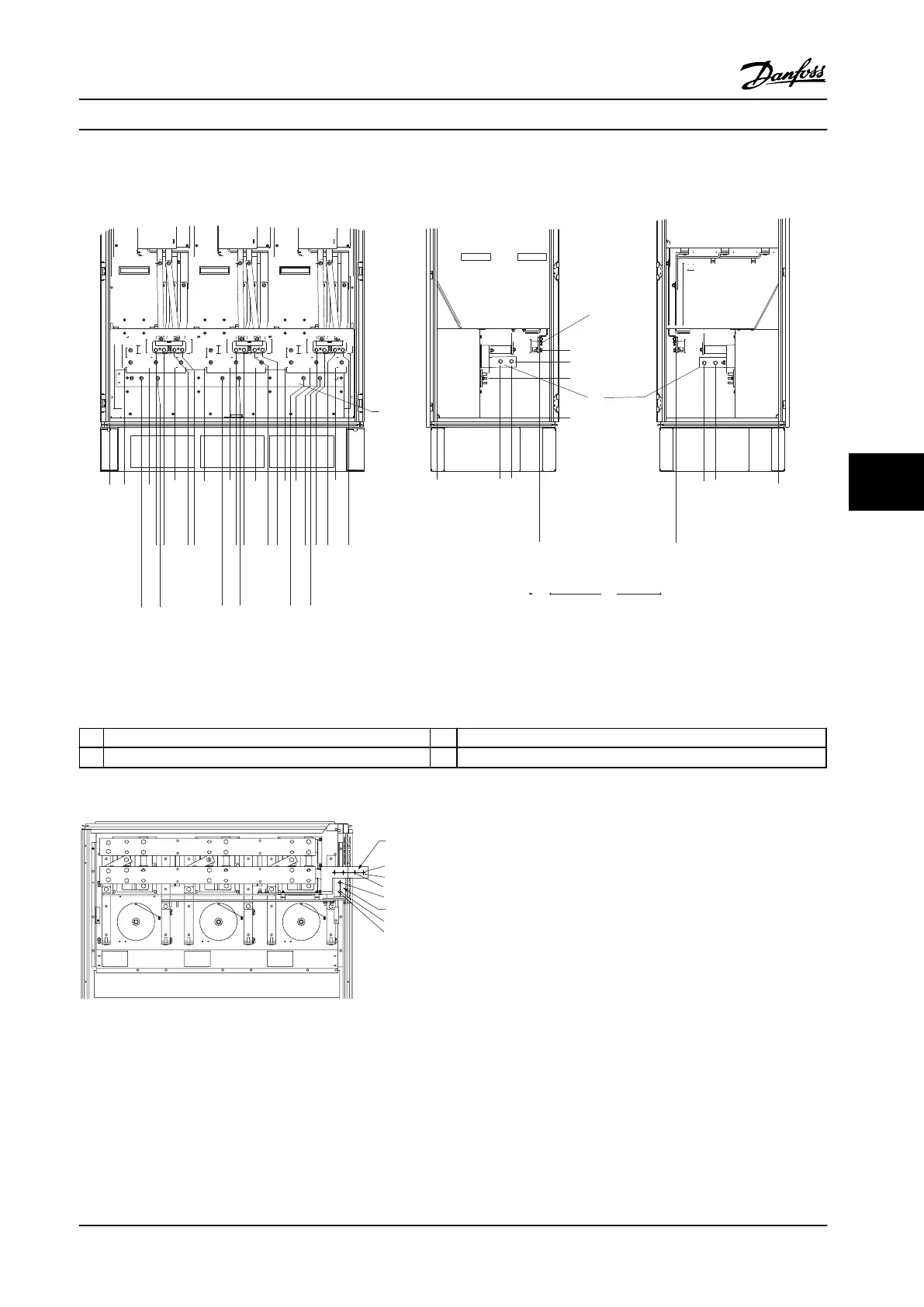
Terminal Locations - Frame Size F2 and F4
Take the following position of the terminals into consideration when designing the cable access.
287.4 [11.32]
0.0 [0.00]
339.4 [13.36]
253.1 [9.96]
0.0 [0.00]
287.4 [11.32]
0.0 [0.00]
339.4 [13.36]
465.6 [18.33]
465.6 [18.33]
308.3 [12.14]
180.3 [7.10]
210.1 [8.27]
0.0 [0.00]
66.4 [2.61]
181.4 [7.14]
296.4 [11.67]
431.0 [16.97]
546.0 [21.50]
661.0 [26.03]
795.7 [31.33]
910.7 [35.85]
1025.7 [40.38]
246.1 [9.69]
294.1 [11.58]
330.1 [13.00]
574.7 [22.63]
610.7 [24.04]
658.7 [25.93]
694.7 [27.35]
939.4 [36.98]
975.4 [38.40]
1023.4 [40.29]
1059.4 [41.71]
144.3 [5.68]
219.3 [8.63]
512.3 [20.17]
587.3 [23.12]
880.3 [34.66]
955.3 [37.61]
6
4
130BA850.12
FASTENER TORQUE: MIO 19 Nm (14 FT -LB)
U/T1 96 V/T2 97 W/T3 98
FASTENER TORQUE: MIO 19 Nm (14 FT -LB)
U/T1 96 V/T2 97 W/T3 98
FASTENER TORQUE: MIO 19 Nm (14 FT -LB)
U/T1 96 V/T2 97 W/T3 98
1
2
3
4
5
Figure 7.26 Terminal Locations - Inverter Cabinet - F2 and F4. Connector Plate is 1.65 in [42 mm] below .0 Level.
1
Front Side 3 Right Side
2 Left Side 4 Ground bar
Table 7.19 Legend to Figure 7.26
S1 S2
S2
F1
F1
S2F1
DC ‘-’
DC ‘+’
1739.1
1203.2
1163.2
1694.1
1654.1
1098.1
130BB378.10
Figure 7.27 Regeneration Terminal Locations - F2 and F4
Electrical Installation Design Guide
MG34S222 Danfoss A/S © Rev. 2014-02-10 All rights reserved. 201
7 7

 Loading...


