Terminal Locations - Rectifier (F1, F2, F3 and F4)
Take the following position of the terminals into consideration when designing the cable access.
74.6 [2.9]
0.0 [0.0]
125.8 [4.95]
218.6 [8.61]
293.6 [11.56]
362.6 [14.28]
437.6 [17.23]
149.6 [5.89]
486.6 [19.16]
183.4 [7.22]
373.4 [14.70]
0.0 [0.00]
70.4 [2.77]
193.9 [7.64]
343.1 [13.51]
38.1 [1.50]
0.0 [0.00]
90.1 [3.55]
136.6 [5.38]
188.6 [7.42]
B
A
435.5 [17.15]
LOAD SHARE LOCATION
DIM F1/F2 F3/F4
A 380.5 [14.98] 29.4 [1.16]
B 432.5 [17.03] 81.4 [3.20]
6
5
4
130BA848.12
CH22 CH22
R/L1 91 S/L2 92
FASTENER TORQUE: M8 9.6 Nm (7 FT-LB)
T/L3 93
FASTENER TORQUE: M10 19 Nm (14 FT-LB)
FASTENER TORQUE: M10 19 Nm (14 FT-LB)
DC 89
FASTENER TORQUE: M10 19 Nm (14 FT-LB)
DC 89
CH22 CH22 CH22 CH22
CTI25MB CTI25MB
AUXAUXAUXAUXAUX
3
2
1
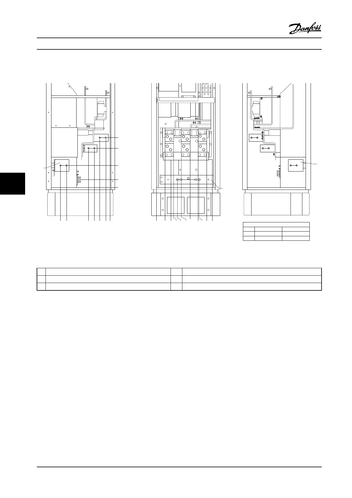
Figure 7.28 Terminal Locations - Rectifier. Connector Plate is 1.65 in [42 mm] below .0 Level.
1
Left Side 4 Load share Terminal (-)
2 Front Side 5 Ground bar
3 Right Side 6 Load share Terminal (+)
Table 7.20 Legend to Figure 7.28
Electrical Installation Design Guide
202 Danfoss A/S © Rev. 2014-02-10 All rights reserved. MG34S222
77

 Loading...


