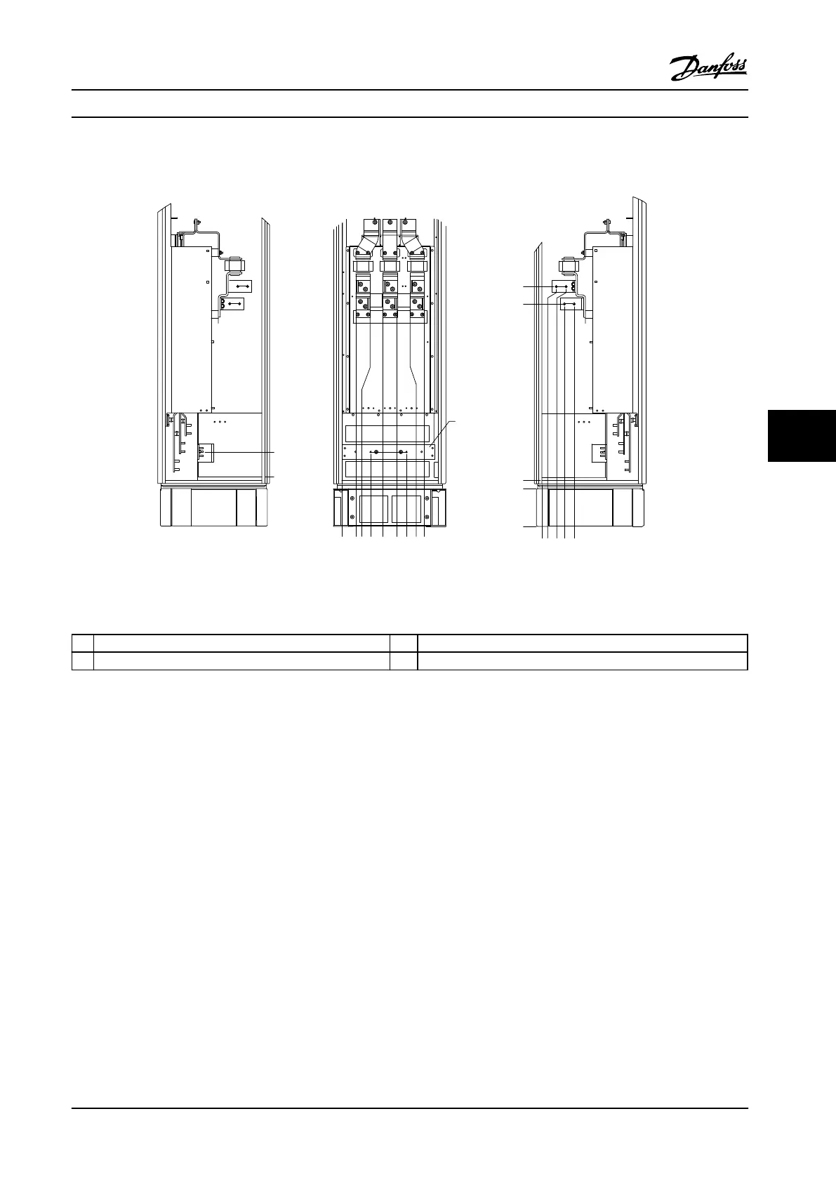
Terminal Locations - Options Cabinet (F3 and F4)
Take the following position of the terminals into consideration when designing the cable access.
1 2 3
4
0.0[0.00]
76.4[3.01]
128.4[5.05]
119.0[4.69]
171.0[6.73]
294.6[11.60]
344.0[13.54]
3639[14.33]
438.9[17.28]
75.3[2.96]
150.3[5.92]
154.0[6.06]
219.6[18.65]
0.0[0.00]
244.4[9.62]
244.4[1.75]
939.0[36.97]
1031.4[40.61]
0.0[0.00]
134.6[5.30]
130BA851.12
0.0[1.75]
Figure 7.29 Terminal Locations - Options Cabinet. Connector Plate is 1.65 in [42 mm] below .0 Level.
1
Left Side 3 Right Side
2 Front Side 4 Ground bar
Table 7.21 Legend to Figure 7.29
Electrical Installation Design Guide
MG34S222 Danfoss A/S © Rev. 2014-02-10 All rights reserved. 203
7 7

 Loading...


