* F10/F11/F12/F13 Only
* F10/F11/F12/F13 Only
91-1
92-1
93-1
91-2
92-2
93-2
S1
T1
R1
S2
T2
R2
95
Rectier 1
Rectier 2
Inverter1
F8/F9
Inverter2
F10/F11
Inverter3
F12/F13
130BB758.11
91-1
92-1
93-1
91-2
92-2
93-2
S1
T1
R1
S2
T2
R2
95
Rectier 1
Rectier 2
Inverter1
F8/F9
Inverter2
F10/F11
Inverter3
F12/F13
91-1
92-1
93-1
91-2
92-2
93-2
95
Rectier 1
Rectier 2
Inverter1
Inverter2
F10/F11
Inverter3
F12/F13
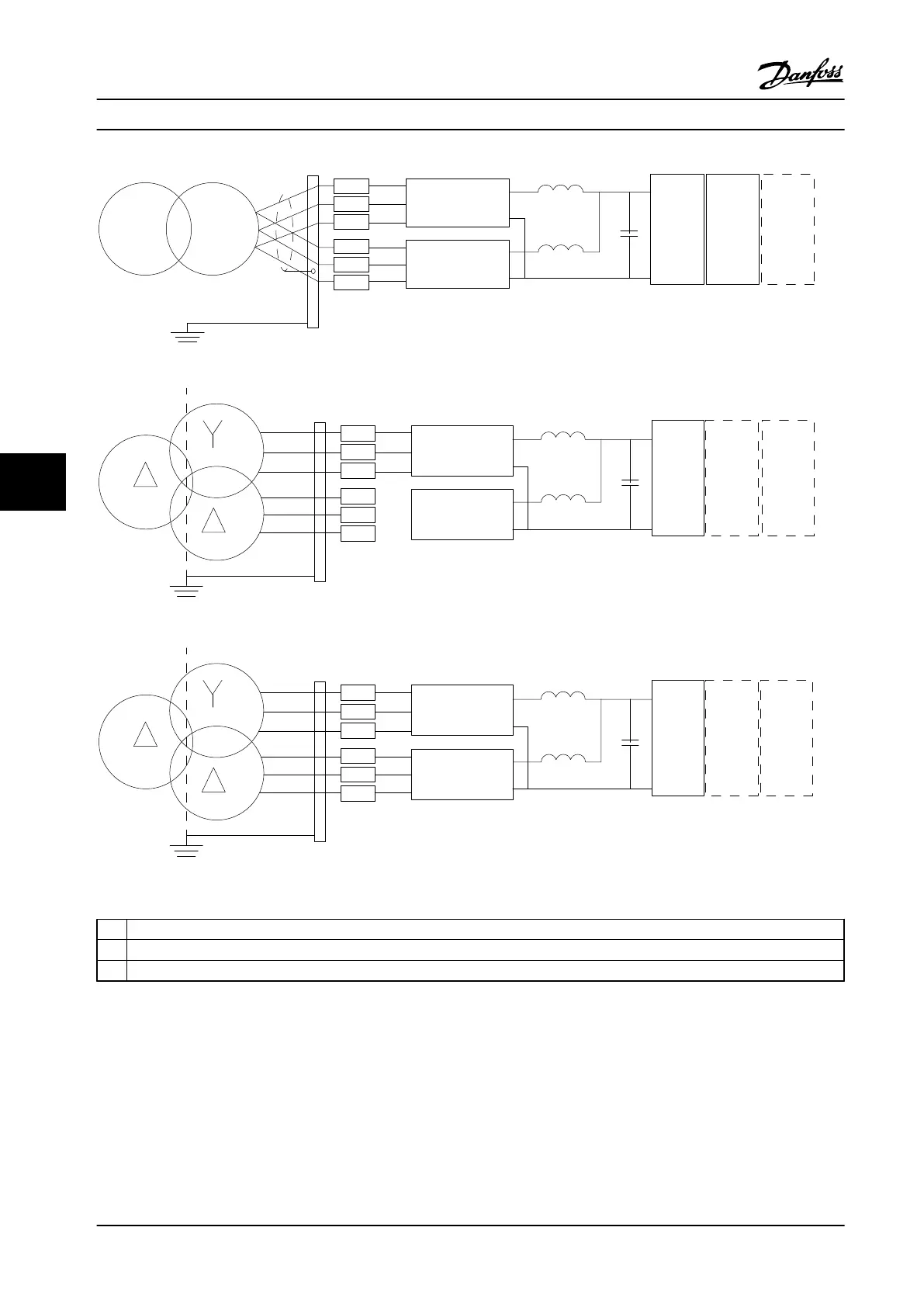
A
B
C
Figure 7.32 AC Line Input Connection Options for 12-Pulse Adjustable Frequency Drives
A
6-Pulse Connection
1), 2), 3)
B
Modified 6-Pulse Connection
2), 3), 4)
C
12-Pulse Connection
3), 5)
Table 7.24 Legend to Figure 7.32
Notes:
1)
Parallel connection shown. A single 3-phase cable may be used with sufficient carrying capability. Install shorting bus bars.
2)
6-pulse connection eliminates the harmonics reduction benefits of the 12-pulse rectifier.
3)
Suitable for IT and TN AC line input connection.
4)
If one of the 6-pulse modular rectifiers becomes inoperable, it is possible to operate the adjustable frequency drive at
reduced load with a single 6-pulse rectifier. Contact Danfoss for reconnection details.
5)
No paralleling of line power cabling is shown here. A 12-pulse adjustable frequency drive used as a 6-pulse should have
line cables of equal numbers and lengths.
Electrical Installation
Design Guide
206 Danfoss A/S © Rev. 2014-02-10 All rights reserved. MG34S222
77

 Loading...


