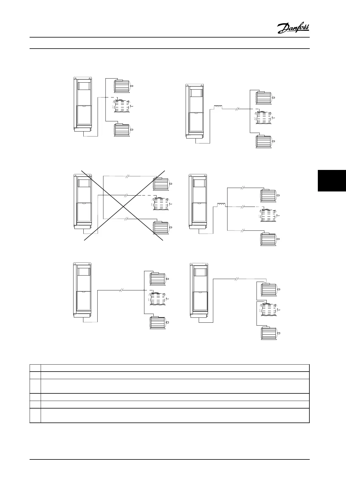
Figure 7.34 Different Parallel Connections of Motors
A
Installations with cables connected in a common joint as shown in A and B are only recommended for short cable lengths.
B
Be aware of the maximum motor cable length specified in chapter 4.3 General Specifications.
C
The total motor cable length specified in chapter 4.3 General Specifications is valid as long as the parallel cables are kept short less
than 10 m each. (Example 1).
D Consider voltage drop across the motor cables. (Example 1).
E Consider voltage drop across the motor cables. (Example 2).
F
The total motor cable length specified in chapter 4.3 General Specifications is valid as long as the parallel cables are kept less than
10 m each. (Example 2).
Table 7.65 Legend to Figure 7.34
Electrical Installation
Design Guide
MG34S222 Danfoss A/S © Rev. 2014-02-10 All rights reserved. 221
7 7

 Loading...


