The relay option does not support FC 302 adjustable
frequency drives manufactured before week 50/2004.
Min. software version: 2.03 (15-43 Software Version).
2
130BA709.11
1
LABEL
Remove jumper to activate Safe Stop
12
13
18
19
27
29
33
32
20
39
42
50
53
54
61
68
CAUTION:
SEE MANUAL / RCD and high leakage current
VOIR MANUAL / Fransk tekst
WARNING:
Stored charge / “Fransk tekst” (4 min.)
LISTED 76x1 134261
INDUSTRIAL CONTROL EQUIPMENT
SEE MANUAL FOR PREFUSE TUPE IN UL
APPLICATIONS
T/C : CIAXXXPT5B20BR1DBF00A00
P/N : XXXN1100 S/N: 012815G432
IN: 3x380-480V 50/60Hz 14.9A
OUT: 3x0-Uin 0-1000Hz 16.0A 11.1 kVA
CHASIS/IP20 Tamb Max 45C/113F
MADE IN DENMARK
9Ø
9Ø
Ø6
Figure 9.9 A2, A3, and B3
2
130BA710.11
1
LABEL
Remove jumper to activate Safe Stop
13
12
18
19
27
32
38
2
28
42
39
53
50
5
61
6
9Ø
9Ø
DC-
DC+
Figure 9.10 A5, B1-B4, and C1-C4
1)
IMPORTANT! The label MUST be placed on the LCP
frame as shown in Figure 9.10 to meet UL approval.
WARNING
Warning Dual supply. Do not combine 24/48 V systems
with high voltage systems.
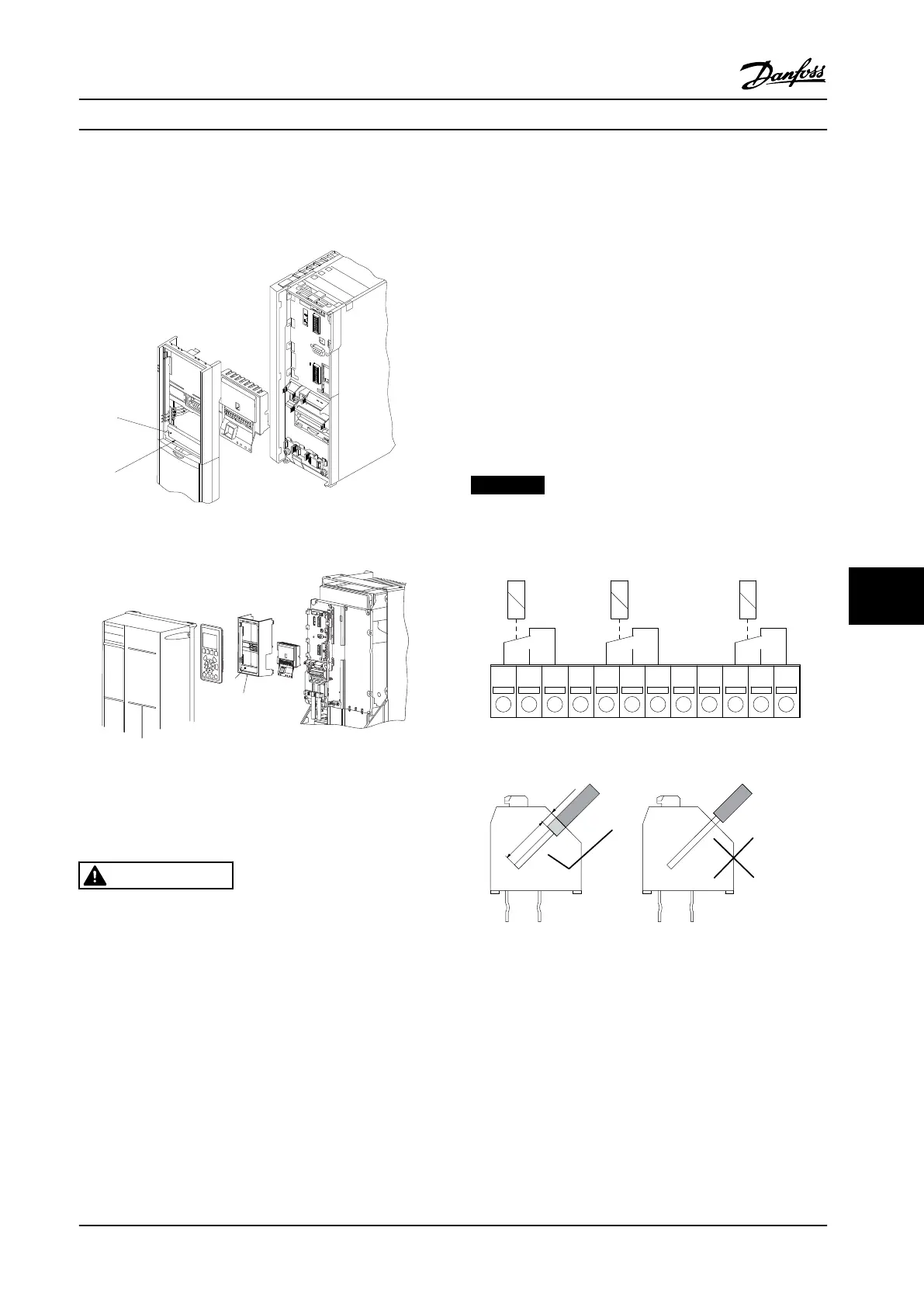
To add the MCB 105 option, perform the following steps:
•
The power to the adjustable frequency drive
must be disconnected. For discharge times, see
the instructions supplied with this option
•
The power to the live part connections on relay
terminals must be disconnected. See Figure 9.11
•
Remove the LCP, the terminal cover, and the LCP
fixture from the adjustable frequency drive
•
Fit the MCB 105 option in slot B
•
Connect the control cables and fasten the cables
with the enclosed cable strips.
•
Make sure the length of the stripped wire is
correct. See Figure 9.12
•
Do not mix the live parts (high voltage) with the
control signals (PELV). See Figure 9.13
•
Fit the enlarged LCP fixture and enlarged
terminal cover
•
Replace the LCP.
•
Connect power to the adjustable frequency drive
•
Select the relay functions in 5-40 Function Relay
[6-8], 5-41 On Delay, Relay [6-8] and 5-42 Off
Delay, Relay [6-8].
NOTICE!
Array [6] is relay 7, array [7] is relay 8, and array [8] is
relay 9.
Relay 7
NC NCNC
Relay 9Relay 8
1 2 3 12
130BA162.10
754 6 8 9 10 11
Figure 9.11 Disconnect Relay Terminals
Figure 9.12 Proper Length of Stripped Wire
Options and Accessories Design Guide
MG34S222 Danfoss A/S © Rev. 2014-02-10 All rights reserved. 257
9 9

 Loading...


