1
2
z
z
z
L1
L2
L3
PE
U
V
W
C
S
I
2
I
1
I
3
I
4
C
S
C
S
C
S
C
S
I
4
C
S
z
PE
3
4
5
6
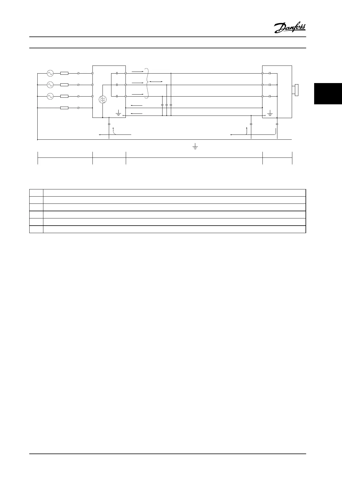
Figure 3.26 Leakage Currents
1 Ground wire
2 Shield
3 AC line power supply
4 Adjustable frequency drive
5 Shielded motor cable
6 Motor
Table 3.13 Legend to Figure 3.26
Figure 3.26 shows an example of a 6-pulse adjustable frequency drive, but could be applicable to a 12-pulse as well.
If placing the shield on a mounting plate, use a metal plate because the shield currents must be conveyed back to the
adjustable frequency drive. Ensure good electrical contact from the mounting plate through the mounting screws to the
adjustable frequency drive chassis. When non-shielded cables are used, some emission requirements are not complied with,
although the immunity requirements are observed.
To reduce the interference level from the entire system (unit and installation), make motor and brake cables as short as
possible. Avoid placing cables with a sensitive signal level alongside motor and brake cables. Radio interference higher than
50 MHz (airborne) comes from the control electronics. For more information on EMC, see chapter 7.8 EMC-compatible Instal-
lation.
Product Introduction Design Guide
MG34S222 Danfoss A/S © Rev. 2014-02-10 All rights reserved. 47
3 3

 Loading...


