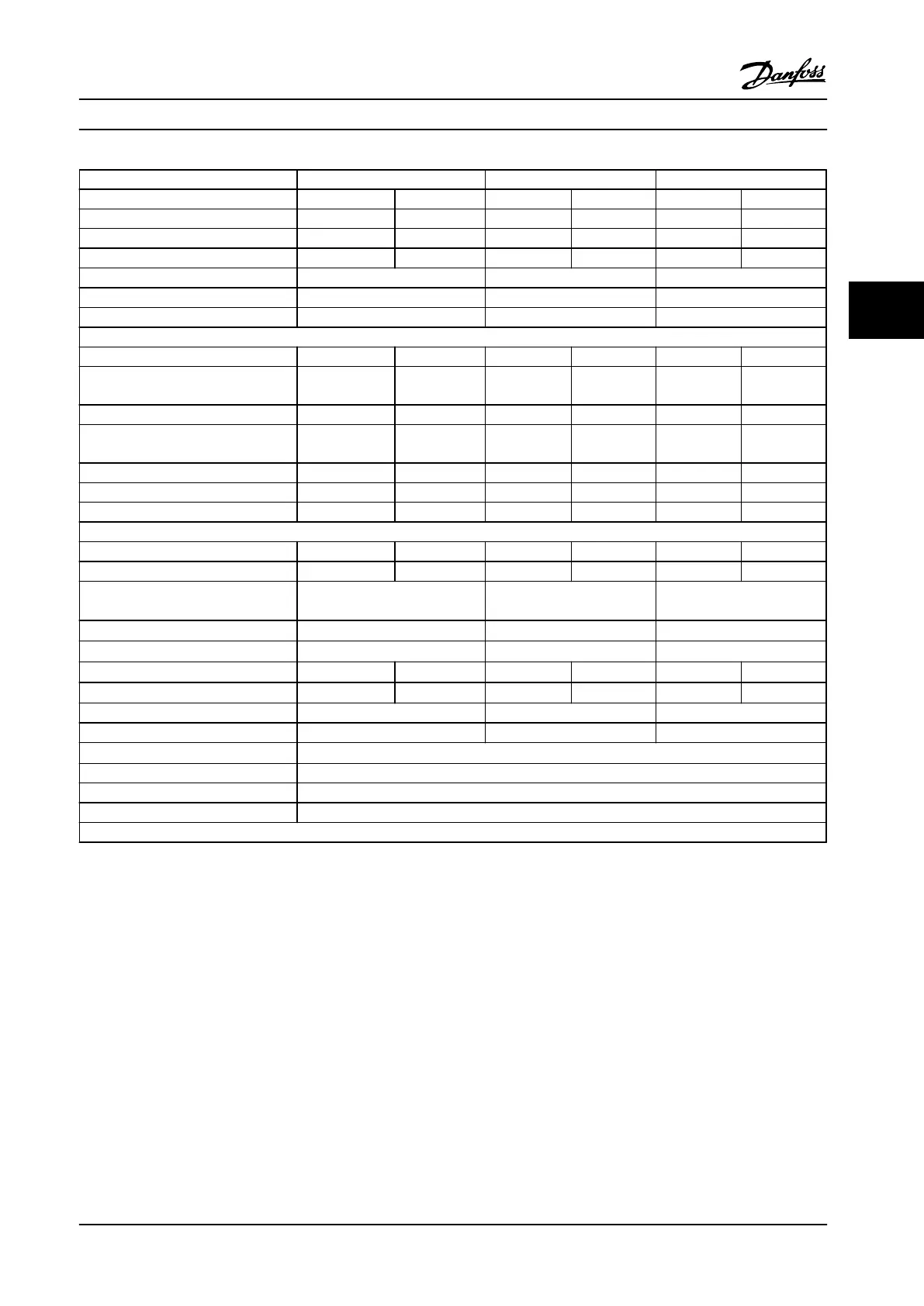
FC 302 P315 P355 P400
High/Normal load* HO NO HO NO HO NO
Typical shaft output at 400 V [kW] 315 355 355 400 400 450
Typical shaft output at 460 V [HP] 450 500 500 600 550 600
Typical shaft output at 500 V [kW] 355 400 400 500 500 530
Enclosure IP21 E1 E1 E1
Enclosure IP54 E1 E1 E1
Enclosure IP00 E2 E2 E2
Output current
Continuous (at 400 V) [A] 600 658 658 745 695 800
Intermittent (60 s overload)
(at 400 V) [A]
900 724 987 820 1043 880
Continuous (at 460/500 V) [A] 540 590 590 678 678 730
Intermittent (60 s overload)
(at 460/500 V) [A]
810 649 885 746 1017 803
Continuous kVA (at 400 V) [kVA] 416 456 456 516 482 554
Continuous kVA (at 460 V) [kVA] 430 470 470 540 540 582
Continuous kVA (at 500 V) [kVA] 468 511 511 587 587 632
Maximum input current
Continuous (at 400 V) [A] 590 647 647 733 684 787
Continuous (at 460/500 V) [A] 531 580 580 667 667 718
Max. cable size, line power, motor and
load share [mm
2
(AWG)]
1)2)
4x240 (4x500 mcm) 4x240 (4x500 mcm) 4x240 (4x500 mcm)
Max. cable size, brake [mm
2
(AWG)
1)
2x185 (2x350 mcm) 2x185 (2x350 mcm) 2x185 (2x350 mcm)
Max. external electrical fuses [A]
3)
900 900 900
Estimated power loss at 400 V [W]
4)
5)
6794 7532 7498 8677 7976 9473
Estimated power loss at 460 V [W]
4) 5)
6118 6724 6672 7819 7814 8527
Weight, enclosure IP21, IP54 [kg] 270 272 313
Weight, enclosure IP00 [kg] 234 236 277
Efficiency
5)
0.98
Output frequency 0–590 Hz
Heatsink overtemp. trip 230 °F [110 °C]
Control card ambient trip 185 °F [85 °C]
* High overload=160% torque during 60 s, Normal overload=110% torque during 60 s.
Table 4.2 Technical Specifications, E-frame 380–500 V Line Power Supply 3x380–500 V AC
1) American Wire Gauge.
2) Wiring terminals on N132, N160, and P315 adjustable frequency drives cannot receive cables one size larger.
3) For fuse ratings, see chapter 7.2.1 Fuses.
4) Typical power loss is at normal conditions and expected to be within
±
15% (tolerance relates to variety in voltage and cable conditions.) These
values are based on a typical motor efficiency (IE/IE3 border line). Lower efficiency motors add to the power loss in the adjustable frequency drive.
If the switching frequency is raised from nominal, the power losses rise significantly. LCP and typical control card power consumptions are
included. Options and customer load can add up to 30 W to the losses, though usually a fully loaded control card and options for slots A and B
each add only 4 W.
5) Measured using 16.5 ft. [5 m] shielded motor cables at rated load and rated frequency.
Selection
Design Guide
MG34S222 Danfoss A/S © Rev. 2014-02-10 All rights reserved. 65
4 4

 Loading...


