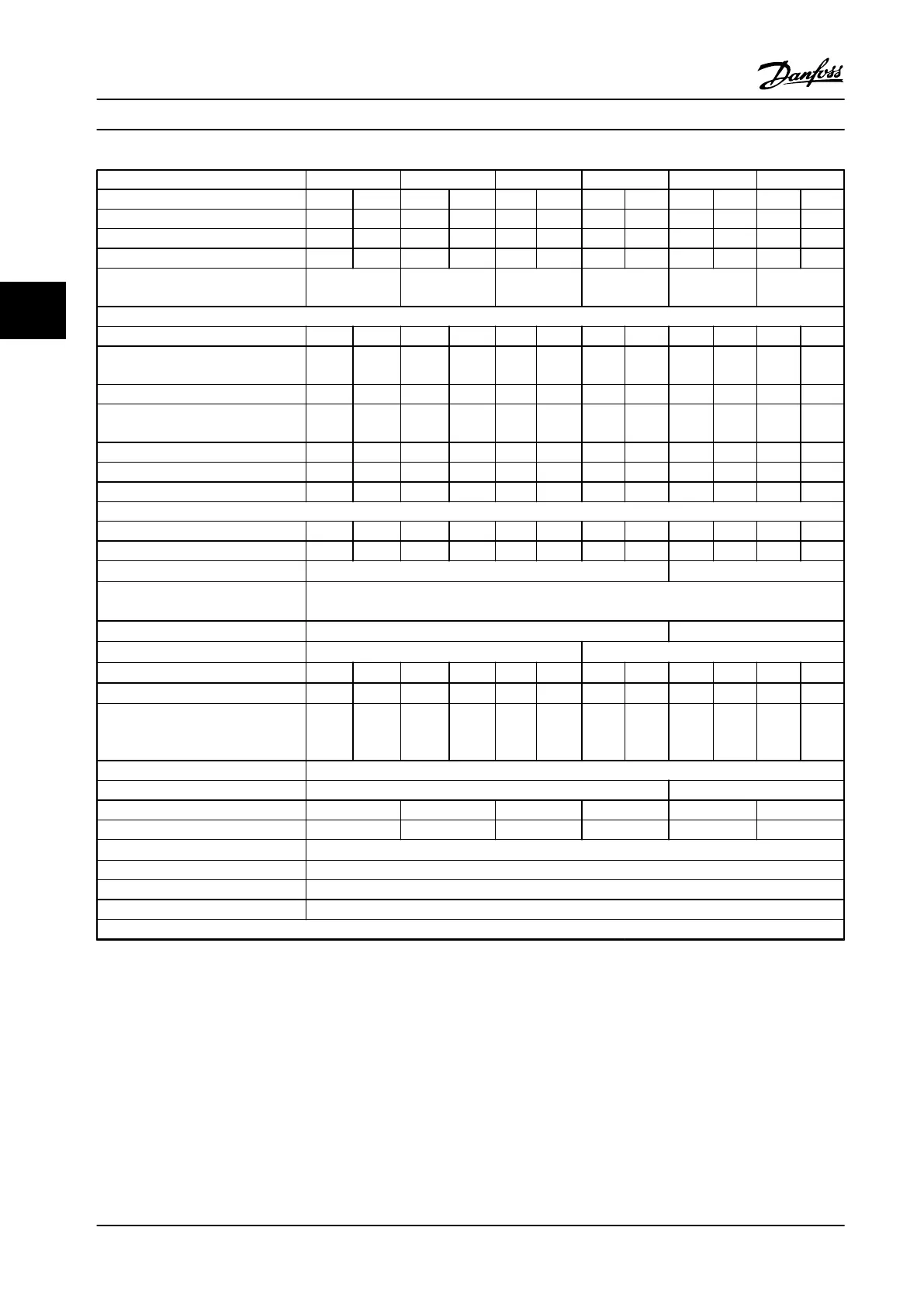
FC 302 P450 P500 P560 P630 P710 P800
High/Normal load * HO NO HO NO HO NO HO NO HO NO HO NO
Typical shaft output at 400 V [kW] 450 500 500 560 560 630 630 710 710 800 800 1000
Typical shaft output at 460 V [HP] 600 650 650 750 750 900 900 1000 1000 1200 1200 1350
Typical shaft output at 500 V [kW] 530 560 560 630 630 710 710 800 800 1000 1000 1100
Enclosure IP21, IP54 without/with
options cabinet
F10/F11 F10/F11 F10/F11 F10/F11 F12/F13 F12/F13
Output current
Continuous (at 400 V) [A] 800 880 880 990 990 1120 1120 1260 1260 1460 1460 1720
Intermittent (60 s overload)
(at 400 V) [A]
1200 968 1320 1089 1485 1232 1680 1386 1890 1606 2190 1892
Continuous (at 460/500 V) [A] 730 780 780 890 890 1050 1050 1160 1160 1380 1380 1530
Intermittent (60 s overload)
(at 460/500 V) [A]
1095 858 1170 979 1335 1155 1575 1276 1740 1518 2070 1683
Continuous KVA (at 400 V) [KVA] 554 610 610 686 686 776 776 873 873 1012 1012 1192
Continuous KVA (at 460 V) [KVA] 582 621 621 709 709 837 837 924 924 1100 1100 1219
Continuous KVA (at 500 V) [KVA] 632 675 675 771 771 909 909 1005 1005 1195 1195 1325
Maximum input current
Continuous (at 400 V) [A] 779 857 857 964 964 1090 1090 1227 1227 1422 1422 1675
Continuous (at 460/500 V) [A] 711 759 759 867 867 1022 1022 1129 1129 1344 1344 1490
Max. cable size, motor [mm
2
(AWG)
1)
]
8x150 (8x300 mcm) 12x150 (12x300 mcm)
Max. cable size, line power
[mm
2
(AWG)
1)
]
6x120 (6x250 mcm)
Max. cable size, brake [mm
2
(AWG)
1)
]
4x185 (4x350 mcm) 6x185 (6x350 mcm)
Max. external electrical fuses [A]
2)
900 1500
Estimated power loss at 400 V [W]
3)
4)
9492 10647 10631 12338 11263 13201 13172 15436 14967 18084 16392 20358
Estimated power loss at 460 V [W]
3)
4)
8730 9414 9398 11006 10063 12353 12332 14041 13819 17137 15577 17752
F9/F11/F13 max. added losses A1 RFI,
CB or disconnect, & contactor
F9/F11/F13
893 963 951 1054 978 1093 1092 1230 2067 2280 2236 2541
Max. panel options losses 400
Weight, enclosure IP21, IP54 [kg] 1017/ 1319 1261/ 1562
Weight, rectifier module [kg] 102 102 102 102 136 136
Weight, inverter module [kg] 102 102 102 136 102 102
Efficiency
4)
0.98
Output frequency 0–590 Hz
Heatsink overtemp. trip 203 °F [95 °C]
Power card ambient trip 185 °F [85 °C]
* High overload=160% torque during 60 s, Normal overload=110% torque during 60 s.
Table 4.5 Technical Specifications, F10-F13 frames, 380–500 V Line Power Supply 6x380–500 V AC, 12-Pulse
1) American Wire Gauge.
2) For fuse ratings, see chapter 7.2.1 Fuses.
3) Typical power loss is at normal conditions and expected to be within
±
15% (tolerance relates to variety in voltage and cable conditions.) These
values are based on a typical motor efficiency (IE/IE3 border line). Lower efficiency motors add to the power loss in the adjustable frequency drive.
If the switching frequency is raised from nominal, the power losses rise significantly. LCP and typical control card power consumptions are
included. Options and customer load can add up to 30 W to the losses, though usually a fully loaded control card and options for slots A and B
each add only 4 W.
4) Measured using 16.5 ft. [5 m] shielded motor cables at rated load and rated frequency.
Selection
Design Guide
68 Danfoss A/S © Rev. 2014-02-10 All rights reserved. MG34S222
44

 Loading...


