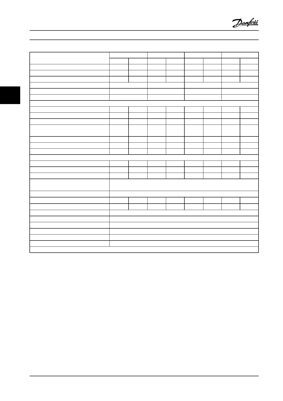
FC 302 High/Normal load* N160 N200 N250 N315
HO NO HO NO HO NO HO NO
Typical Shaft output at 550 V [kW] 132 160 160 200 200 250 250 315
Typical Shaft output at 575 V [hp] 200 250 250 300 300 350 350 400
Typical Shaft output at 690 V [kW] 160 200 200 250 250 315 315 400
Enclosure IP21 D2h D2h D2h D2h
Enclosure IP54 D2h D2h D2h D2h
Enclosure IP20 D4h D4h D4h D4h
Output current
Continuous (at 550 V) [A] 201 253 253 303 303 360 360 418
Intermittent (60 s overload) (at 550 V) [A] 302 278 380 333 455 396 540 460
Continuous (at 575/690 V) [A] 192 242 242 290 290 344 344 400
Intermittent (60 s overload) (at 575/690 V)
[kVA]
288 266 363 319 435 378 516 440
Continuous kVA (at 550 V) [kVA] 191 241 241 289 289 343 343 398
Continuous kVA (at 575 V) [kVA] 191 241 241 289 289 343 343 398
Continuous kVA (at 690 V) [kVA] 229 289 289 347 347 411 411 478
Maximum input current
Continuous (at 550 V) [A] 198 245 245 299 299 355 355 408
Continuous (at 575 V) [A] 189 234 234 286 286 339 339 390
Continuous (at 690 V) 197 240 240 296 296 352 352 400
Max. cable size: line power, motor, brake and
load share mm
2
(AWG)
1)
2x185 (2x350)
Max. external electrical fuses [A]
2)
550
Estimated power loss at 575 V [W]
3)
4)
2361 3074 3012 3723 3642 4465 4146 5028
Estimated power loss at 690 V [W]
3)
4)
2446 3175 3123 3851 3771 4614 4258 5155
Weight, enclosure IP21, IP54 kg (lbs) 125 (275)
Weight, enclosure IP20 kg (lbs) 125 (275)
Efficiency
4)
0.98
Output frequency 0–590 Hz
Heatsink overtemperature trip 230 °F [110 °C]
Control card ambient trip 176 °F [80 °C]
*High overload=150% current for 60 s, Normal overload=110% current for 60 s.
Table 4.7 Technical Specifications, D-frame, 525–690 V Line Power Supply 3x525–690 V AC
1) American Wire Gauge.
2) For fuse ratings, see chapter 7.2.1 Fuses.
3) Typical power loss is at normal conditions and expected to be within
±
15% (tolerance relates to variety in voltage and cable conditions.) These
values are based on a typical motor efficiency (IE/IE3 border line). Lower efficiency motors add to the power loss in the adjustable frequency drive.
If the switching frequency is raised from nominal, the power losses rise significantly. LCP and typical control card power consumptions are
included. Options and customer load can add up to 30 W to the losses, though usually a fully loaded control card and options for slots A and B
each add only 4 W.
4) Measured using 16.5 ft. [5 m] shielded motor cables at rated load and rated frequency.
Selection
Design Guide
70 Danfoss A/S © Rev. 2014-02-10 All rights reserved. MG34S222
44

 Loading...


