INSTALLATION
16
SAFERY LASER SCANNER
Minimum Safety Distance Calculations for Horizontal Applications
NOTE
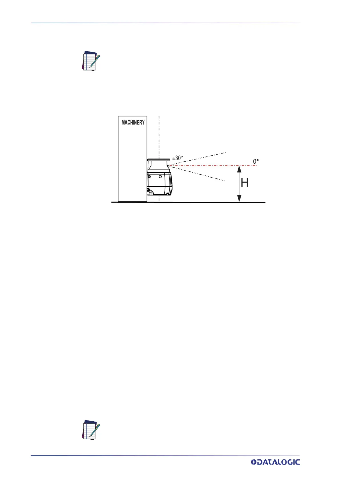
If the device is mounted with a detection angle of less than 30° with respect to the hori-
zontal plane (floor), the application is considered horizontal (parallel approach).
Figure 4 - Detection plane and approaching direction
The minimum safety distance S is given by:
S = (K*T) + C; C
MIN
= 850 mm; H
MIN
= 15(d – 50 mm)
Where:
S =
Minimum safety distance (mm)
K =
1600 mm/s
T =
t
1
+ t
2
C = C
HEIGHT
+ C
TOLERANCE
+ C
AMBIENT INTERF
C
MIN
= Lowest allowable C value
t
1
= Response time of the ESPE (s) (refer to "Response Time and Scan Cycle Setting"
on page 62
)
t
2
= Machine stopping time (s) (see machine specifications)
C
HEIGHT
≥ (1200 – 0.4H) mm
H = Height of the nominal scan plane with respect to the machine refer-
ence plane (floor) (mm)
H
MIN
= Lowest allowable height of the detection zone (mm)
d = Detection capability of the ESPE (mm)
C
TOLERANCE
= 100 mm
C
AMBIENT INTERF
= environment interference conditions (mm) (refer to "Light Inter-
ference" on page 12
and "High Reflecting Background" on page 13)
NOTE
The Minimum Safety Distance cannot exceed the nominal maximum limit of
the Safety Zone for the scanner (5.5 m).
For applications with approach parallel to the detection plane, EN ISO
13855 defines the parameter K = 1600 mm/s.