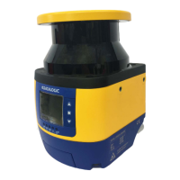
LASER SENTINEL STAND ALONE MODEL CONNECTORS
INSTRUCTION MANUAL
39
Machine Interface Connections
The Laser Sentinel Stand Alone model has one OSSD pair and three signals programma-
ble as inputs and outputs. These signals allow the user to
configure the device with sev-
eral functions:
• the detection of a person or an object in the Warning Zone,
• the switching of the detection areas by employing external signals (Area Switch),
• the restart of the device caused by the OSSD Off-status (Restart),
• restoring the device after a failure condition (Reset),
• the automatic deactivation of the safety status on the whole safety zone (Muting),
• the Single line pattern Muting Override used to force the safety function deactiva-
tion whenever it is necessary to restart the machine.
NOTE
NOTE
Figure 1 - Connector (M12, 8-pole Male)
The Multi In/Out is a Pin that can be configured either as input or output.
RESTART/RESET
AREA SWITCH
OVERRIDE (Single line pattern)
MUTING 1 MUTING 2
MUTING ENABLE
MULTI-OUT WARNING
MUTING LAMP
OSSD OSSD 1/1 OSSD 1/2
For further information about the device functions, refer to Chapter 8,
Functions.
Make sure that the signals are aligned with the pin features and their spe-
cific function. In addition, they must be correctly connected to the external
device.
CATEGORY TYPE COLOR DESCRIPTION PIN OUT
POWER
POWER SUPPLY BROWN 24Vdc 2
GND_ISO BLUE 0 V 7
INPUT/OUTPUT
MULTI IN/OUT GREEN Selectable by GUI 3
MULTI IN/OUT YELLOW Selectable by GUI 4
MULTI IN/OUT WHITE Selectable by GUI 1
SAFETY
OUTPUTS
OSSD 1/1 GRAY Safety Output 5
OSSD 1/2 PINK Safety Output 6
OTHER F_EARTH RED Functional Earth 8
TYPE FUNCTION CONNECTION
MULTI-IN
 Loading...

