MASTER CONNECTION
INSTRUCTION MANUAL
41
MASTER CONNECTION
The Master model includes a configurable set of input and outputs that have a specific
purpose and it depends on the selected topology and pin configuration.
Through the GUI, the user can choose the type of configuration. The operator must fol-
low the indications for the type of pin selected and the safety standards.
NOTE
NOTE
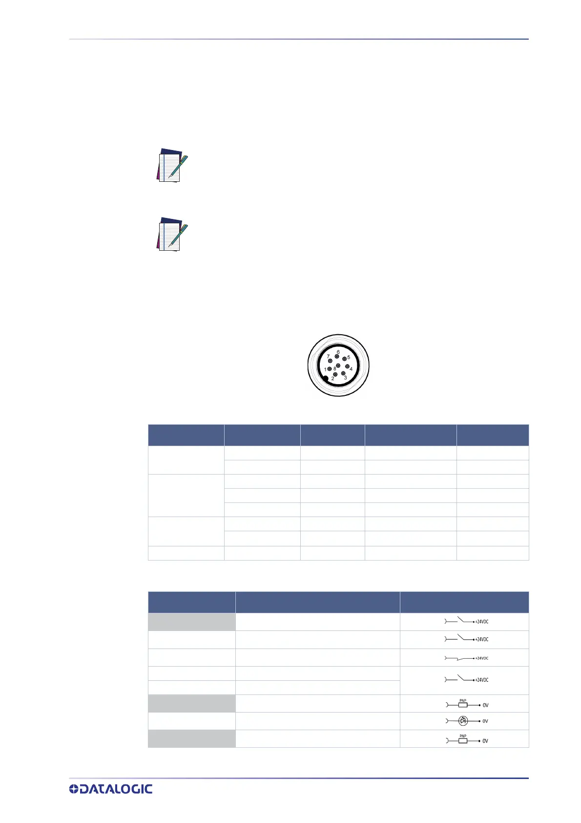
Master M12 8-Pole Connector
The Master M12 8-pole model has various pin typologies. The features of all the electri-
cal pins are showed in the chart below.
Figure 2 - Connector (M12, 8-pole Male)
The Multi In/Out is a Pin that can be configured either as input or output.
RESTART/RESET
AREA SWITCH
OVERRIDE (Single line pattern)
MUTING 1 MUTING 2
MUTING ENABLE
MULTI-OUT WARNING
MUTING LAMP
OSSD OSSD 1/1 OSSD 1/2
Input and output connected to the Laser Sentinel must be aligned with the
features of the used pin.
8-pole and 12-pole connectors cannot be used together, but just individu-
ally according to application needs.
CATEGORY TYPE COLOR DESCRIPTION PIN OUT
POWER
POWER SUPPLY BROWN 24Vdc 2
GND_ISO BLUE 0 V 7
INPUT/OUTPUT
MULTI IN GREEN Selectable by GUI 3
MULTI IN YELLOW Selectable by GUI 4
MULTI IN/OUT WHITE Selectable by GUI 1
SAFETY
OUTPUTS
OSSD 1/1 GRAY Safety Output 5
OSSD 1/2 PINK Safety Output 6
OTHER F_EARTH RED Functional Earth 8
TYPE FUNCTION CONNECTION
MULTI-IN