LASER SENTINEL: THE SLAVE
INSTRUCTION MANUAL
49
LASER SENTINEL: THE SLAVE
To create the Laser Sentinel network, the operator has to connect the Slave devices.
These are equipped with rotatable side connectors for the input and output connection
and will receive data and power supply from the previous devices which in turn will
send it to the others.
NOTE
NOTE
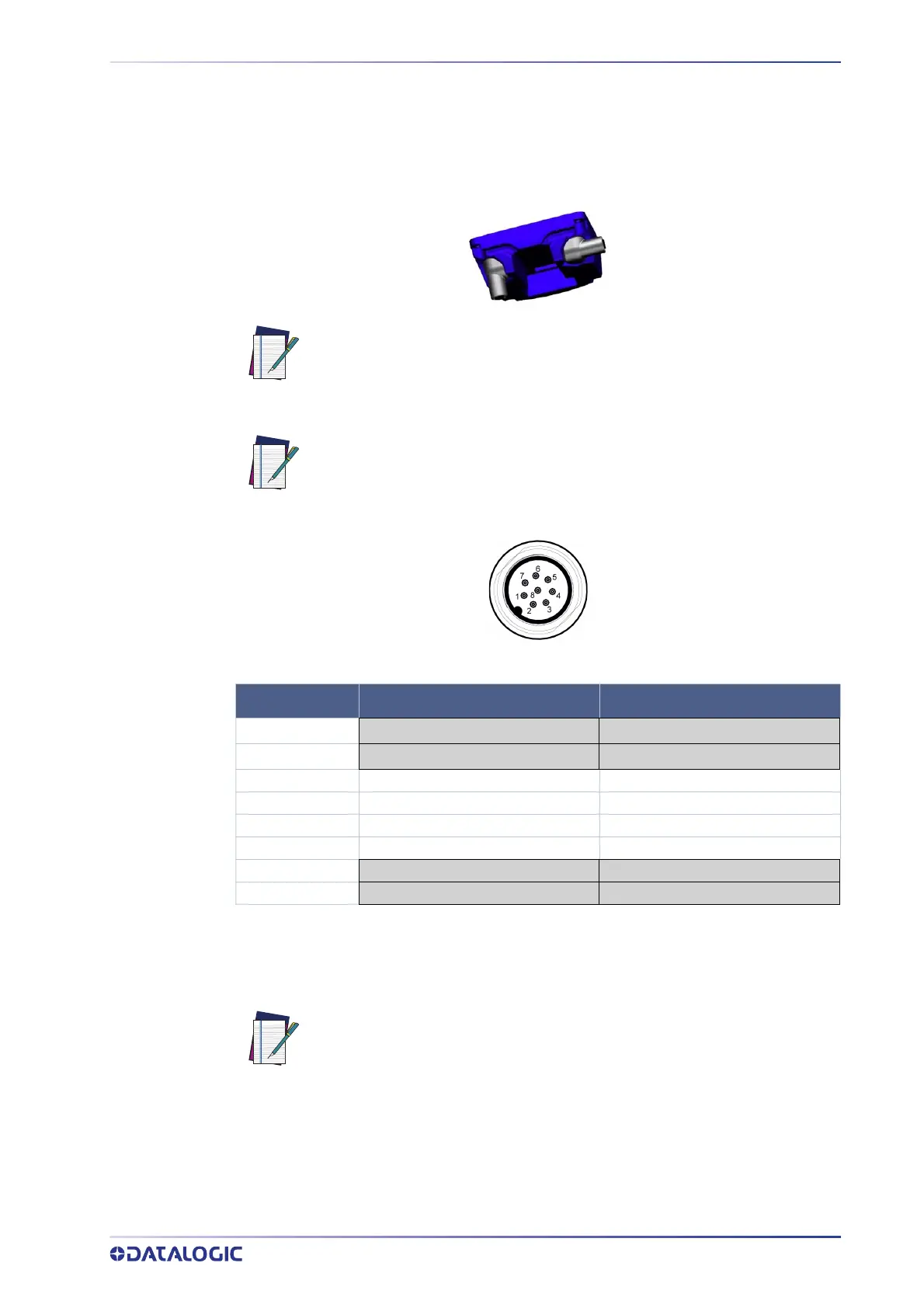
Figure 6 - Connector (M12, 8-pole Male)
For the configuration of the Laser Sentinel Master/Slave, the operator must connect the
Master to the PC (on which the GUI is installed). Before connecting the Master, make
sure that the Slave devices are connected by following the correct order established in
advance.
NOTE
It is possible to connect from one to max. three devices at a time.
Use 8-pole connectors to connect the Slave devices.
PIN OUT INPUT PORT OUTPUT PORT
1
V
PWR
V
PWR
7
V
PWR
V
PWR
6I_TX+ O_TX+
5I_RX+ O_RX+
4I_TX- O_TX-
8I_RX- O_RX-
2
GND_ISO GND_ISO
3
GND_ISO GND_ISO
All the devices must be switched off during the connection. By supplying
power to the Master, all the connected slaves will be switched on automat-
ically.
 Loading...