ELECTRICAL CONNECTIONS
40
SAFERY LASER SCANNER
MASTER SLAVE SYSTEM CONNECTION
The Laser Sentinel series includes various models that differ in some features, such as
electrical configuration and connection type.
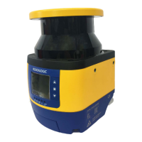
There are two main safety laser scanner models: the Master (that can be used individu-
ally or to run other slave devices) and the Slave (that must be connected to a Master
and has only a particular co
nnection to be connected to its Ethernet network).
On one side, the device is equipped with M12 connector socket, on the other side, the
opera
tor must employ free wires in compliance with the Laser Sentinel pinout colors.
Datalogic provides the wires in compliance with the regulations and standards for a safe
use of the Laser Se
ntinel (refer to
Appendix C, Accessories).
The Master (see
Figure 1 on page xiii) includes:
• M12 8-pole connector
• M12 12-pole connector
• M12 17-pole connector
• M12 4-pole rotatable side connector (LAN connection)
• M12 8-pole rotatable side connector (for the connection to the Slave network)
The Sl
ave (see
Figure 2 on page xiv) includes:
• M12 8-pole rotatable side connector (Input Port)
• M12 8-pole rotatable side connector (Output Port)
NOTE
For power and I/O cables (8 poles, 12 poles, and 17 poles), you must
unmount the memory group as described in "
Memory Group Unmounting
for Cable Connection" on page 35.
 Loading...

