MECHANICAL MOUNTING
30
SAFERY LASER SCANNER
ANGLE ADJUSTMENT BRACKET MOUNTING
First, provide two M5 holes with 73 mm spacing on the intended wall or mounting sur-
face.
NOTE
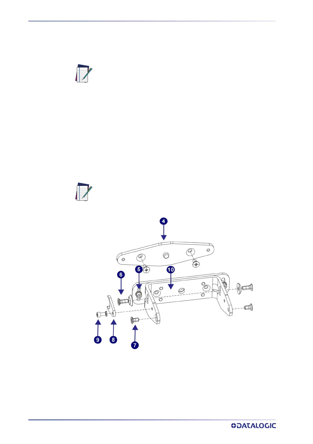
Pitch and Roll Angle Adjustment Bracket (SLS-BRACKET-A)
The bracket system (10) is partially assembled.
1. Mount the roll adjustment bracket (4) t
o the wall or panel by inserting two M5
UNI 5933 screws (not included), and tighten them, repeatedly alternating
between one and the other, until they are completely tight.
2. After removing the M4 screws and washers (5
) from the roll adjustment bracket
(4), use them to assemble the support bracket (10) to the roll adjustment bracket
(4).
NOTE
Figure 4 - Pitch and Roll Angle Adjustment Bracket
The M5 UNI 5933 screws used for mounting the brackets to a wall are not
supplied in the SLS bracket mounting kits; they must be supplied by the
user.
Still, do not tighten the M4 Roll Adjustment screws for the roll angle (5).