MEMORY GROUP UNMOUNTING FOR CABLE CONNECTION
INSTRUCTION MANUAL
35
MEMORY GROUP UNMOUNTING FOR CABLE CONNECTION
Follow the Master model’s memory group unmounting procedure to connect the M12
8/12/17-pole connector (according to model) for machine interface.
NOTE
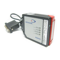
1. Orient the device with the optic head pointed downward to access the underside
of the device
(connectors location).
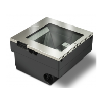
2. Unscrew the two M3 screws of the protective cover, then remove it.
NOTE
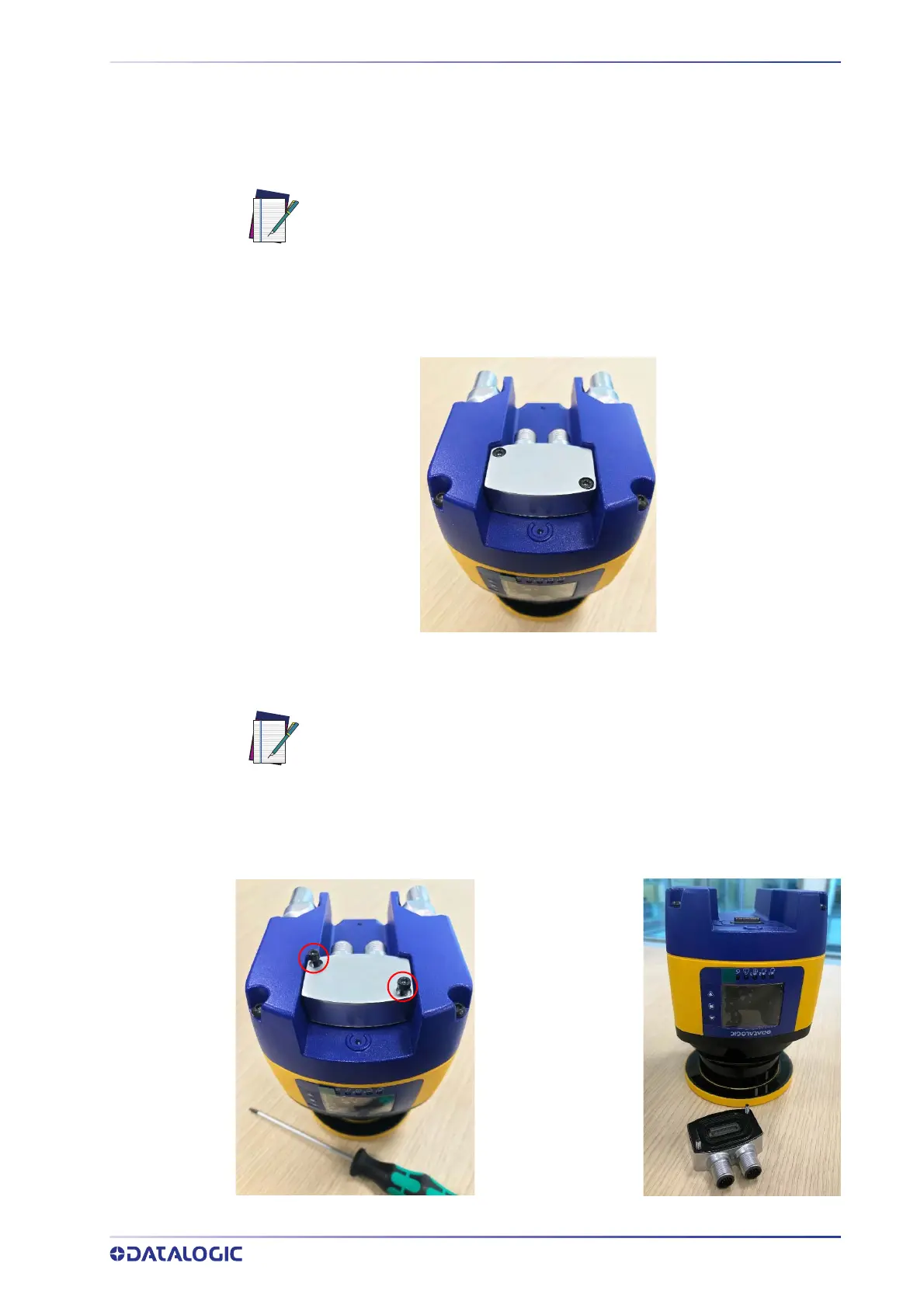
3. Loosen the two M3 fixing screws of the memory group and disconnect the mem-
ory group by extracting it from the scanner.
Adjustable torque driver with 2.5 mm hex key.
The protective cover is tightened with captive screws, so the operator only
has to loosen the screws to extract the cover from the device.