ENCODERS
INSTRUCTION MANUAL
81
In the example above, the EncR value is 10,000 / 125.66 = 79.58 p/cm. Therefore, on
DLSentinel the rounded value “80” must be entered in the relevant Encoder [p/cm]
field. The software will calculate the max. allowed speed based on this data.
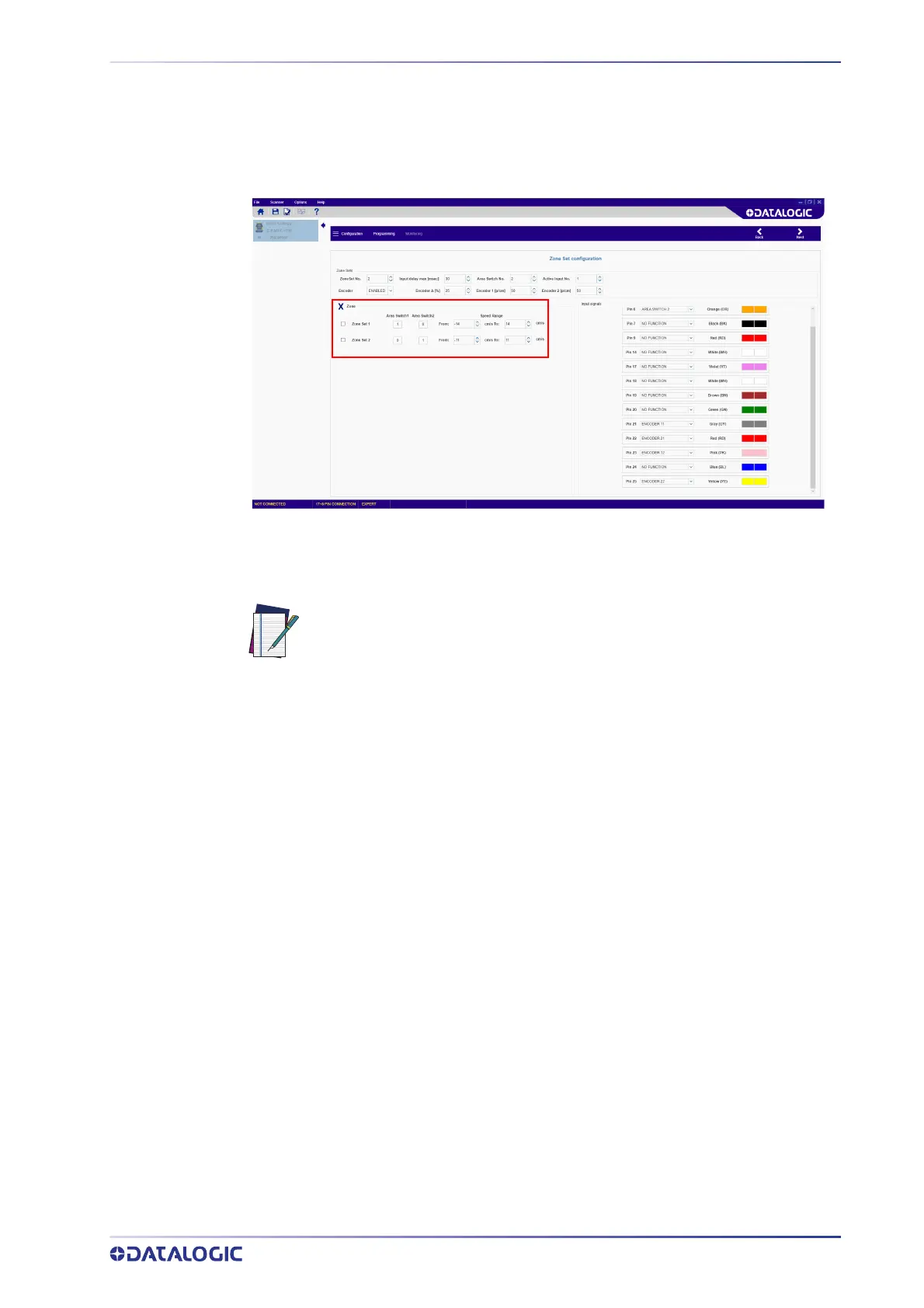
After setting the encoder values, the Zone Sets must be configured.
Zone
This parameter group allows editing the Area Switch input combinations depending on
the number of selected Zone Sets and the Speed Range of each Zone Set.
NOTE
To set valid Speed Ranges for each Zone Set, the user first needs to calculate the maxi-
mum and minimum speeds that the Safety Laser Scanner can read.
To calculate the maximum speed (V
max
), use the following formula:
V
max
= F
max
/ EncR
Where:
F
max
= 100,000. This is a fixed value corresponding to the maximum frequency
that the Laser Scanner can read.
EncR
= Encoder Ratio, i.e. the number of pulses supplied by the encoder per centi-
meter of distance covered by the vehicle.
To calculate the minimum speed (V
min
), use the following formula:
V
min
= - F
max
/ EncR
After calculating V
max
and V
min
of both encoders, take the lower values as a reference.
The Speed Ranges of each Zone Set must not exceed these V
max
and V
min
values.
Example:
Encoder 1 ratio = 50 p/cm
V
max
1 = 100,000 / 50 = 2,000 cm/s
V
min
1 = -100,000 / 50 = - 2,000 cm/s
If a different input switch coding is configured for each Area Switch, the
relevant Zone Sets can have either overlapping or different Speed Ranges.
In this case, all Area Switches must differ by two input bit states (Ham-
ming distance) to be valid.
On the other hand, if more Area Switches share the same input switch cod-
ing, different Speed Ranges must be configured for each Zone Set.

 Loading...