MX-E Series Hardware Guide Setting Up the System
5 Datalogic S.r.l..
Setting Up the System
WARNING: To avoid damage to your unit, never plug in or unplug any cables when the unit power is on. Always shut
down the processor and turn off the power supply first before making any cable changes (see “Turning Off the System” on
page 3).
NOTE: When a new processor is powered on the first time, a monitor, keyboard, and mouse must be connected to the pro-
cessor to approve the license agreement.
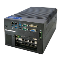
1. Familiarize yourself with the major system components as shown in this manual.
2. Unpack and check all the equipment.
3. Mount the MX-E Series Processor and power supply in their desired positions as indicated in the mounting instruc-
tions (see “Processor Installation” on page 15). Make sure all vents have at least 1.5 inches (38.1 mm) of clearance
for sufficient ventilation.
4. Connect the I/O cable, optional monitor, and optional keyboard to the MX-E Series Processor. Connect the I/O
cable to the terminal block. When a new processor is powered on the first time, a monitor, keyboard, and mouse
must be connected to the processor to approve the license agreement.
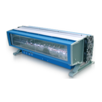
5. Attach the appropriate lens for the application to the camera. Mount the MX-E Series camera, lighting, and
optional power supply. See “Mounting the Camera” on page 29.
NOTE: Do not leave the camera imager uncovered. When you remove the lens cap, you must replace it with a lens.
6. Connect the camera to a Processor GigE port using a Datalogic cable. See “Top Panel Connections” on page 7.
7. You are ready to wire the hardware. See “Processor I/O” on page 99 for details about input/output schematics for
your MX-E Series system. Wiring specifications for all cables are described in “Cable Reference” on page 107.
Storage MX-E20 and MX-E40: 60 GB SATA SSD (MLC)
MX-E80: 128 GB SATA SSD (MLC)
Graphics Intel® HD (1920x1200 resolution) - DVI
PCIe 1 x PCIe x8
Camera Interface MX-E20: 2 x GigE Ethernet ports (PoE capable; enable/disable in VPM-
Settings)
MX-E40 and MX-E80: 2 or 4 x GigE Ethernet ports (PoE capable; enable/
disable in VPM-Settings)
Keyboard/Mouse
USB Ports
4 x USB 3.0 ports
MX-E40 and MX-E80: optional USB 2.0 port
Serial Communication 1 x RS-232 Serial port
Communication Connectivity Supports Ethernet/IP, Modbus, TCP, PROFINET, and OPC
Network interface 2 x LAN ports 10/100/1000 Mbps Base-T
Cable 606-0677-xx
Technical Data