MX-E Series Hardware Guide M565/M570/M575/M580 Camera Connection
39 Datalogic S.r.l.
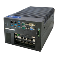
The response times for the strobe output on the M2xx and M3xx cameras will typically fall into the ranges specified
below. The exact response time for your application will depend on the external resistor and the applied voltage you use.
M565/M570/M575/M580 Camera Connection
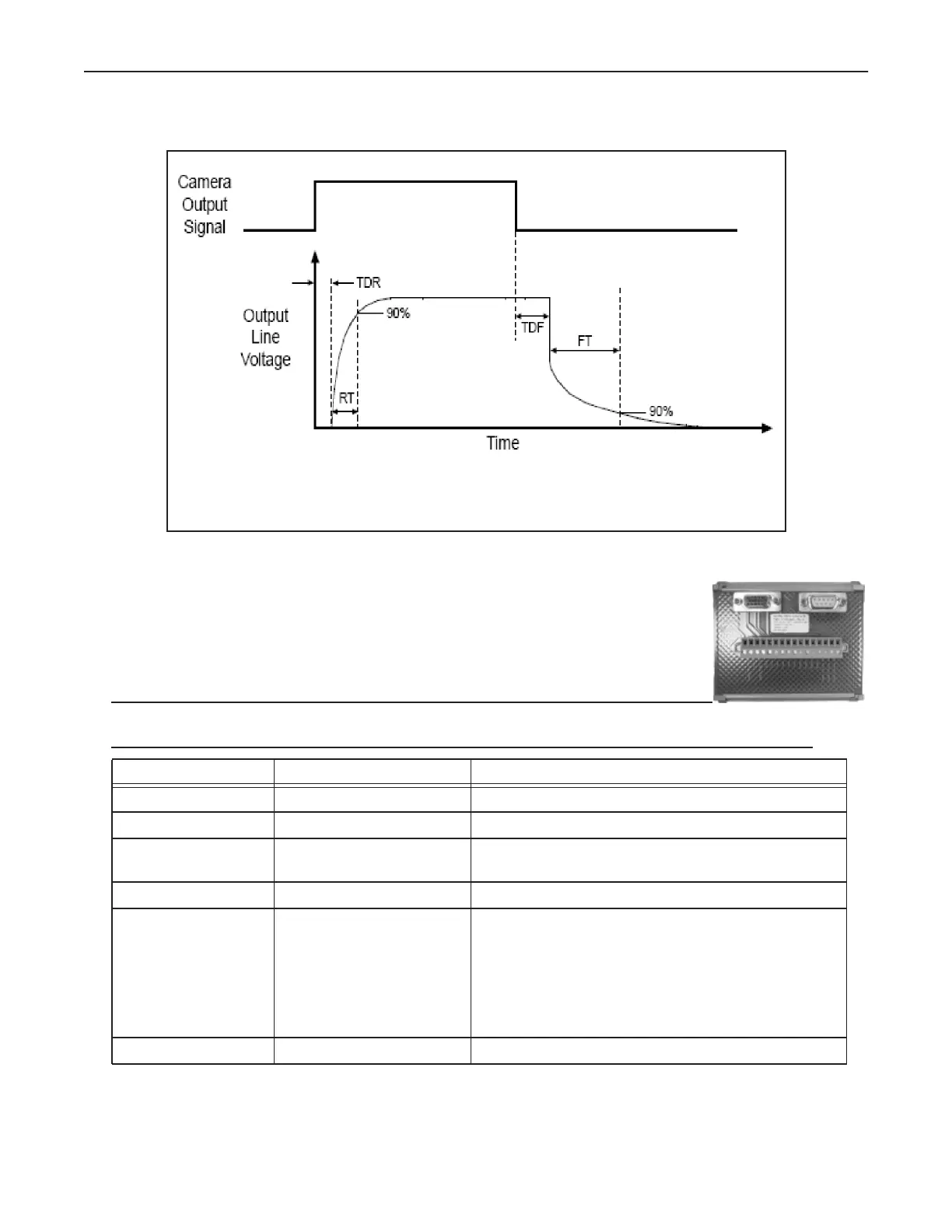
To connect one of these cameras, use terminal block 661-0401 with cable 606-0673-xx (12-pin
to HD-15 camera I/O) and cable 606-0674-xx (6 pin to DB9 camera power). For details about
programming the Line Trigger, refer to the Impact Reference Guide (843-0093)
NOTE: Do NOT use the M2xx/M3xx terminal block (661-0400) or M1xx block (661-0399) to
connect this camera. They will NOT provide the correct signal levels.
Terminal Signal Name Notes
Camera Power Ground Camera Ground See Note 1 Below
I/O Ground I/O Ground See Note 1 Below
Camera Power
+12VDC
Camera Power +12 VDC (+-10%) @ 700 mA Max
Input 1 - No Connection DO NOT USE
Input 1 + Frame Start Trigger As sinking input
Off 0 to +0.8 VDC
On: +2.0 to +5 VDC
As sourcing input (see Input 1 Pullup)
Off: +2.0 to +5 VDC
On 0 to +0.8 VDC
Maximum: +5 VDC
Input 2 - No Connection DO NOT USE
Time Delay Rise (TDR) = 1.5 us
Rise Time (RT) = 1.3 - 5.0 us
Time Delay Fall (TDF) = 1 - 20 us
Fall Time (FT) = 1 - 5 us