Connecting the Camera MX-E Series Hardware Guide
Datalogic S.r.l. 32
Connecting the Camera
WARNING: Never wire M1xx or E1xx Camera Strobe Outputs in parallel with M1xx, E1xx, M2xx, or M3xx Camera
Strobe Outputs. This will damage the cameras.
M1xx and E1xx Camera Connection
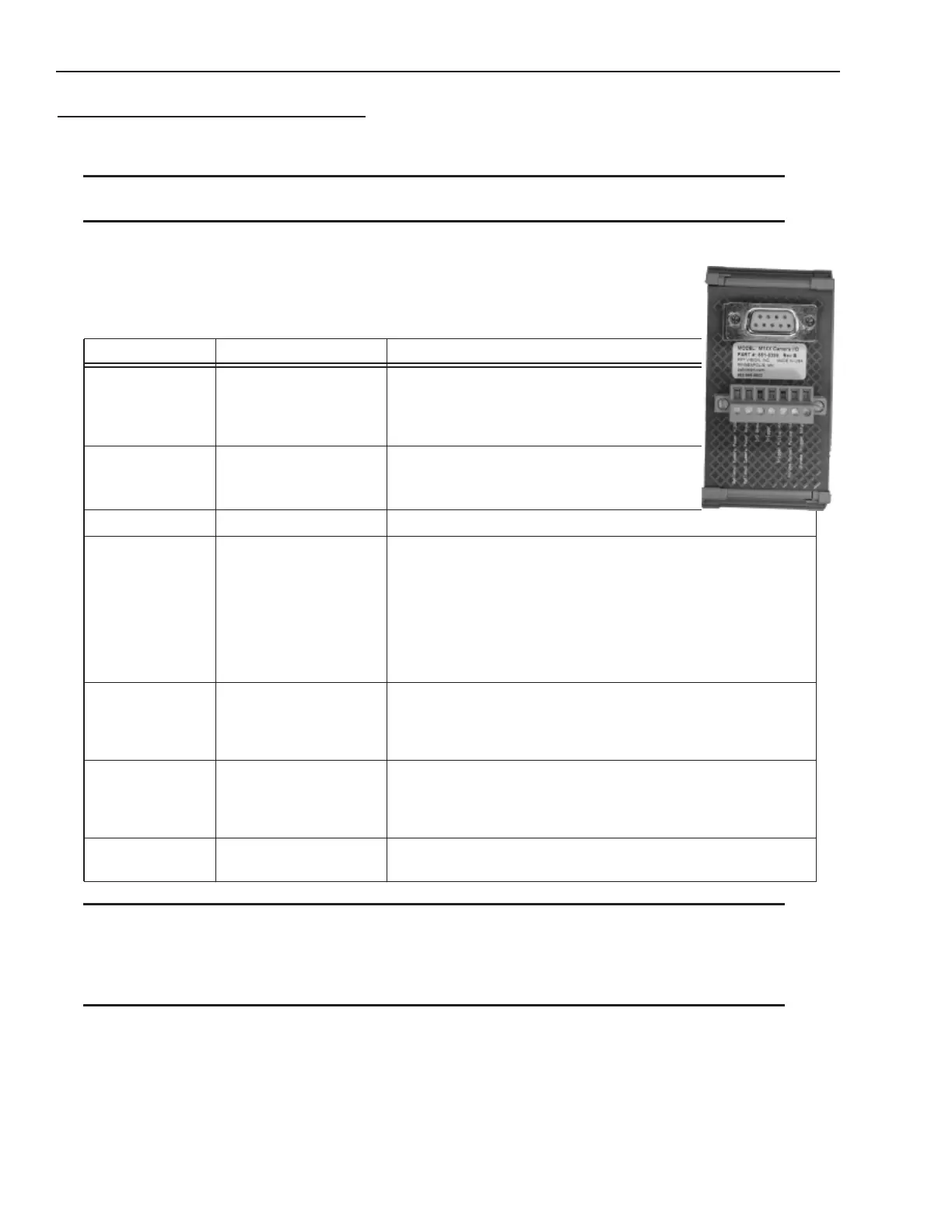
To connect M1xx and E1xx camera trigger signals and strobe outputs, use cable 606-0674-xx (6
pin Hirose Male to DB9) with terminal block 661-0399.
NOTE 1: If Camera Trigger In requires a sinking signal, set the Software Trigger Event to Rising Edge. If it requires a
sourcing signal, set the Software Trigger Event to Falling Edge.
NOTE 2: If Strobe Trigger Output requires a sinking signal, set the Strobe Trigger Output to Falling Edge. If it requires a
sourcing signal, set the Strobe Trigger Output to Rising Edge.
NOTE 3: Disconnecting the camera will turn on some strobe lights.
Terminal Name Signal Notes
Optional Camera
Power
DO NOT USE Do NOT apply power to this terminal if
power is supplied by Power over
Ethernet (PoE
; enable/disable in
VPM-Settings)
Optional Camera
Power Ground
DO NOT USE Not required if ground is supplied by
Power Over Ethernet (PoE
; enable/disable
in VPM-Settings)
I/O Ground I/O Ground
Trigger In** Camera Trigger In 0 to +24 VDC recommended
Maximum +30 VDC
As sinking input
Off: 0 to +1.4 VDC
On: +2.2 to +24 VDC; 5 to 15 ma
As sourcing input (see Trigger Pullup +VCC)
Off: +2.2 to +24 VDC; 5 to 15 ma
On: 0 to +1.4 VDC
Trigger Pullup
+VCC**
Trigger In Pullup - use if
Trigger In needs sourc-
ing (see Note 1 below)
+24 VDC recommended
Maximum +30 VDC
(**Block contains 1.6k Ohm 1W resistor between Trigger In and
Trigger Pullup +VCC)
Strobe Output
Pullup +VCC*
Strobe Supply Voltage -
use if Strobe Trigger
Output needs sourcing
(see Note 2 below)
Based on Strobe requirement (optional)
Max: +30 VDC; 50 ma
(*Block contains 1.6k Ohm 1W resistor between Strobe Trigger
Output and Strobe Output Pullup +VCC)
Strobe Trigger
Output*
Trigger Out to Strobe
(see Note 3 below)
DO NOT APPLY ANY VOLTAGE DIRECTLY TO THIS OUTPUT.
DO NOT WIRE OUTPUTS IN PARALLEL.